Fuel reforming apparatus and its method of driving and fuel cell system including the apparatus

a technology of reforming apparatus and fuel cell, which is applied in the direction of lighting and heating apparatus, indirect heat exchangers, electrochemical generators, etc., can solve the problems of increasing the number of parts of the oxidation reactor using the electric heater, and reducing the life cycle of the entire reforming apparatus. , to achieve the effect of reducing the concentration of carbon monoxid

Inactive Publication Date: 2008-10-30
SAMSUNG SDI CO LTD
View PDF8 Cites 7 Cited by
  • Summary
  • Abstract
  • Description
  • Claims
  • Application Information

AI Technical Summary

Benefits of technology

[0033]The fuel reforming apparatus may further include a carbon monoxide reducing unit having a pipe-type sixth body surrounding the fifth body and reducing the concentration of carbon monoxide in the reformate gas. The combustion gas circulation unit may supply thermal energy of the combustion gas to the carbon monoxide reducing unit.

Problems solved by technology

The burner-type heater has drawbacks of difficulty in driving and reducing a life-cycle of the entire reforming apparatus because a flame causes a hot-spot phenomenon of the burner.
However, particularly when using the gas fuel, the oxidation reactor cannot generate the oxidation reaction of the gas fuel by the oxidation catalyst at room temperature, and therefore the oxidation catalyst needs to be preheated to a predetermined temperature.
However, the conventional oxidation reactor using the electric heater requires an increased number of parts, and consumes power from a fuel cell.
In addition, the conventional oxidation reactor using the burner is difficult to drive so that the oxidation catalyst is sintered or damaged due to the flame.

Method used


Image

  • Fuel reforming apparatus and its method of driving and fuel cell system including the apparatus
  • Fuel reforming apparatus and its method of driving and fuel cell system including the apparatus
  • Fuel reforming apparatus and its method of driving and fuel cell system including the apparatus

Examples


Embodiment Construction

[0054]Hereinafter, the present invention is described more fully with reference to the accompanying drawings, in which exemplary embodiments of the present invention are shown. As those skilled in the art would realize, the described embodiments may be modified in various different ways, all without departing from the spirit or scope of the present invention.

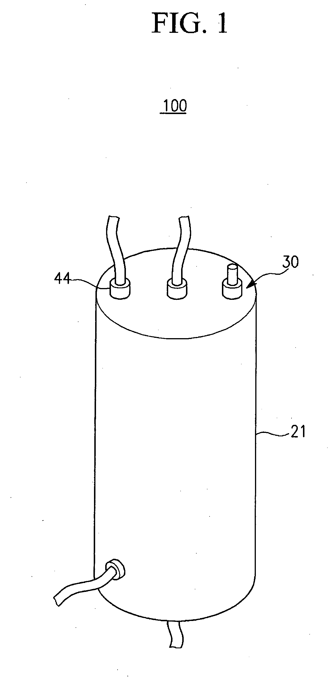
[0055]FIG. 1 is a perspective view of a fuel reforming apparatus according to a first exemplary embodiment of the present invention.

[0056]Referring to FIG. 1, a fuel reforming apparatus 100 according to the first exemplary embodiment of the present invention includes a fuel processor that reforms a fuel and generates a reformate gas that is rich in hydrogen.

[0057]The fuel reforming apparatus 100 supplies a reformate gas to a polymer electrolyte membrane fuel cell, and the polymer electrolyte membrane fuel cell generates electrical energy by using an oxidation reaction of the reformate gas and a reduction reaction of an oxidant (...


PUM

PropertyMeasurementUnit
temperatureaaaaaaaaaa

Abstract

A fuel reforming apparatus includes an oxidation reaction unit in which an oxidation catalyst is formed, a reforming reaction unit in which a reforming catalyst is formed, and an ignition unit for igniting a hydrocarbon-containing fuel and an oxidant and preheating the oxidation catalyst in an early driving stage. The oxidation reaction unit has a first section and a second section respectively formed opposite to each other with the oxidation catalyst interposed therebetween and forms a stream of the fuel and the oxidant flowing to the second section through the oxidation catalyst from the first section, the ignition unit being located in the second section.

Description

CLAIM OF PRIORITY[0001]This application makes reference to, incorporates the same herein, and claims all benefits accruing under 35 U.S.C. §119 from an application for APPARATUS FOR REFORMING FUEL DRIVING METHOD OF THE SAME earlier filed in the Korean Intellectual Property Office on 24 Apr. 2007 and there duly assigned Serial No. 10-2007-0039858.BACKGROUND OF THE INVENTION[0002]1. Field of the Invention[0003]The present invention relates to a reforming apparatus and its method of driving and a fuel cell system including the reforming apparatus. More particularly, the present invention relates to an oxidation reactor that generates thermal energy from an oxidation reaction of a fuel using a catalyst.[0004]2. Description of the Related Art[0005]As is well known, a fuel cell is an electricity generating system for generating electrical energy using a fuel and an oxidant gas. The fuel cell may be either a polymer electrolyte membrane fuel cell or a direct oxidation membrane fuel cell.[0...

Claims


Application Information

Patent Timeline
Patent Type & Authority Applications(United States)
IPC IPC(8): H01M8/18H01M8/04
CPCB01J8/0214B01J8/0257B01J8/0285B01J8/0411B01J8/0465B01J8/0496B01J19/2485B01J2208/00203B01J2208/00309B01J2208/00398C01B3/384C01B3/48C01B2203/0233C01B2203/0283C01B2203/066C01B2203/0811C01B2203/0894C01B2203/1023C01B2203/1035C01B2203/1058C01B2203/107C01B2203/1076H01M8/0618Y02E60/50H01M8/04H01M8/06
Inventor LEE, SUNG-CHULKIM, JU-YONGLEE, YONG-KULHAN, MAN-SEOKKIM, JUN-SIKAHN, JIN-GOO
Owner SAMSUNG SDI CO LTD
Why Eureka
Try Eureka