
Externally Guided and Directed Halbach Array Field Induction Resistivity Tool

a technology of induction resistivity and external guided halbach array, which is applied in the field of measurement procedures to achieve the effect of minimizing the influence of the metal collar or mandrel and minimizing the influence of the collar

Inactive Publication Date: 2008-10-30
SCHLUMBERGER TECH CORP
View PDF38 Cites 18 Cited by
  • Summary
  • Abstract
  • Description
  • Claims
  • Application Information

AI Technical Summary

Benefits of technology

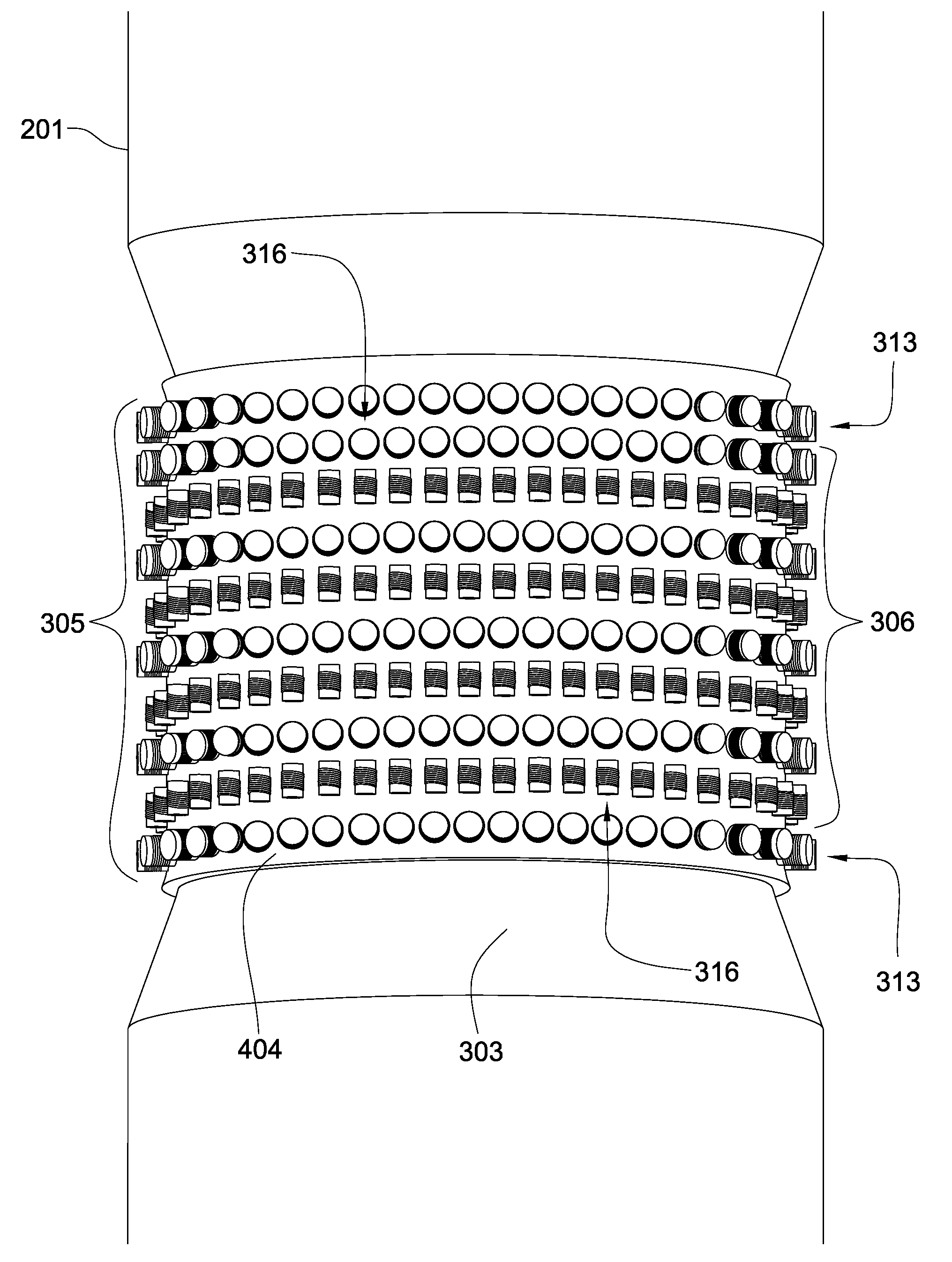
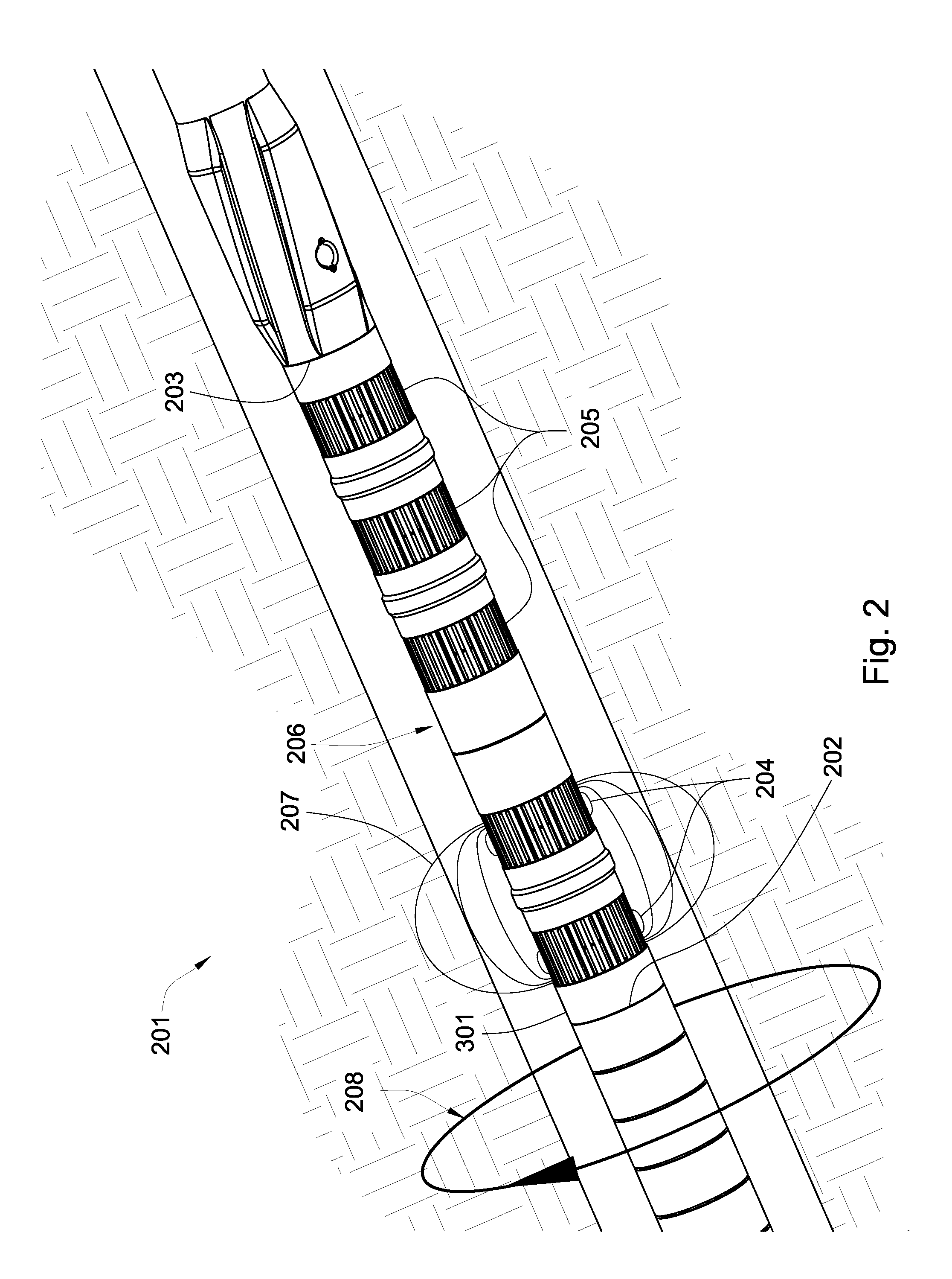
The invention is a configuration of windings, coils, spirals, or antenna that generates a field in a path external to an electrically conductive structure with some electrical and magnetic properties. This allows for the guiding and directing of the field away from the structure, minimizing interference. The invention can be used in padded, pushed, or LWD induction resistivity tools for detailed analysis or smart tool or guided drilling applications. The number of transmitters, receivers, or bucking windings can be adjusted to obtain a given depth of investigation into the formation. The invention can be placed within radial recesses in the collar or mandrel and can be tilted with respect to the downhole tool string.

Problems solved by technology

This fluid exchange increases with time and the formation wall can degrade or become damaged with further drilling operations which can mask or alter information about the formation that is of interest.
The prior art comprises the following references to resistivity tools and resistivity logging which have a common design problem that either allows the transmitted field to penetrate the induction tool or if a shield is utilized, do not actively direct the field away from electrical and magnetic tool surfaces and materials.

Method used


Image

  • Externally Guided and Directed Halbach Array Field Induction Resistivity Tool
  • Externally Guided and Directed Halbach Array Field Induction Resistivity Tool
  • Externally Guided and Directed Halbach Array Field Induction Resistivity Tool

Examples


Embodiment Construction

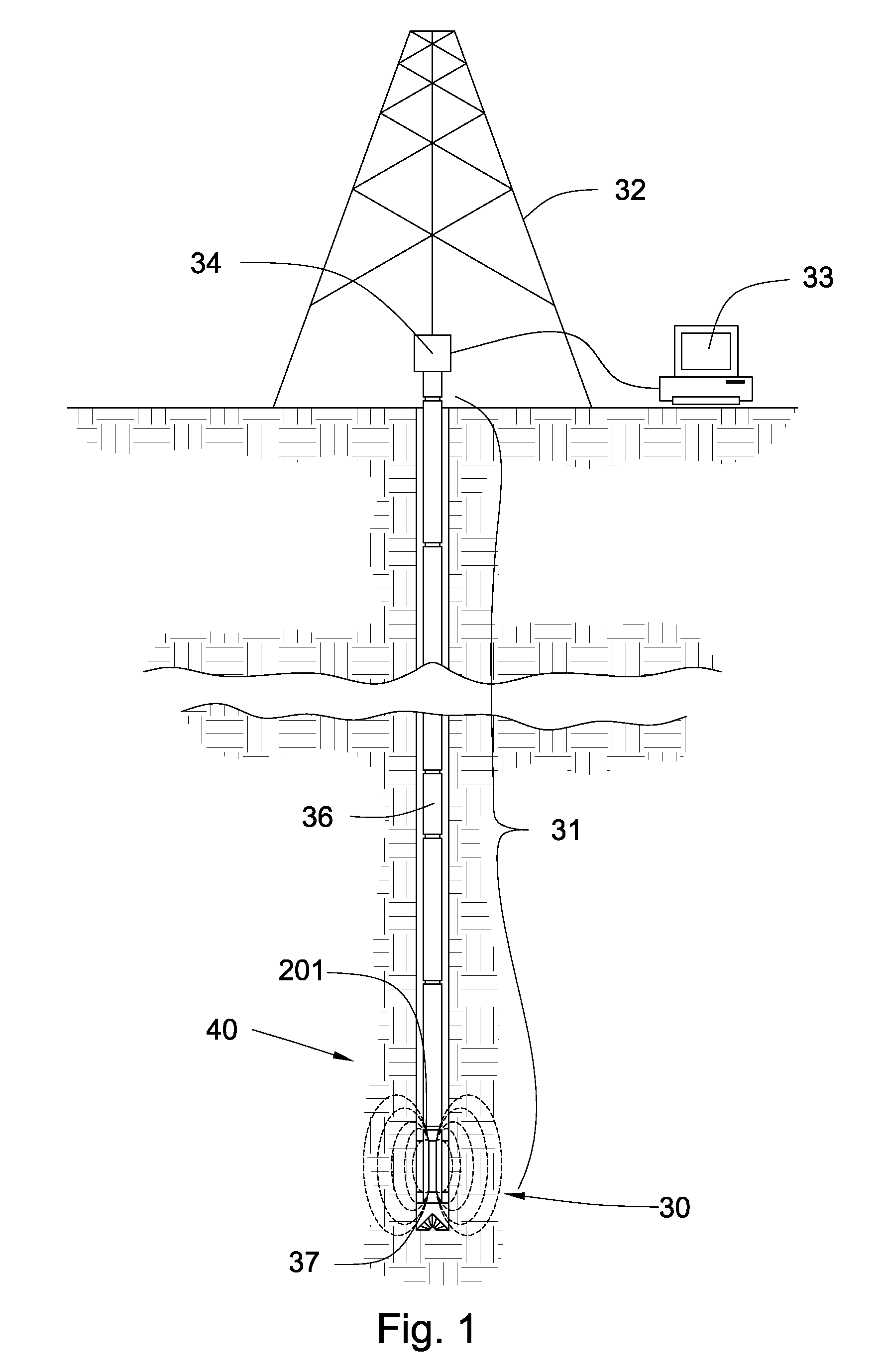
[0036]Referring now to FIG. 1, a downhole tool string 31 may be suspended by a derrick 32. The tool string may comprise one or more downhole components 36, linked together in a tool string 31 and in communication with surface equipment 33 through a downhole network. Having a network in the tool string 31 may enable high-speed communication between each device connected to it and facilitate the transmission and receipt of data between sensors, energy sources, and energy receivers. The tool string 31 is depicted in a vertical drilled hole but it may be at any angle including horizontal.

[0037]The tool string 31 or surface equipment 33 may comprise an energy source or multiple energy sources. The energy source may transmit electrical current to one or more downhole components 36 on the bottom hole assembly 37 or along the tool string 31. In some embodiments of the invention, one or more downhole component 36 may comprise sensors. These sensors may sense gamma rays, radioactive energy, r...


PUM

PropertyMeasurementUnit
induction resistivityaaaaaaaaaa
outer diameteraaaaaaaaaa
magnetic fieldaaaaaaaaaa

Abstract

In one aspect of the invention an induction resistivity tool incorporated into a downhole tool string comprises an outer wall of a downhole component having an outer diameter. At least one induction transmitter assembly is disposed along the outer diameter. The transmitter assembly comprises at least one coil array and at least one induction transmitter coil wound about at least one core. The coil array comprises a plurality of magnetic units and each unit comprising a magnetic field orientation. The magnetic field orientations accumulatively form a Halbach array with an augmented field side and a canceled field side of the array. The transmitter assembly generates an induction signal from outside the outer wall and substantially prevents the signal from entering the outer wall when the transmitter assembly is carrying an electrical current.

Description

CROSS REFERENCE TO RELATED APPLICATIONS[0001]This application is a continuation-in-part of U.S. patent application Ser. No. 11 / 776,447 filed on Jul. 11, 1007 and entitled Externally Guided and Directed Field Induction Resistivity Tool. U.S. patent application Ser. No. 11 / 776,447 is a continuation-in-part of Provisional U.S. Patent Application No. 60 / 914,619 filed on Apr. 27, 2007 and entitled Resistivity Tool. All of the above mentioned references are herein incorporated by reference for all that they contain.BACKGROUND OF THE INVENTION[0002]For the past several decades, engineers have worked to develop apparatus and methods to effectively obtain information about downhole formations, especially during the process of drilling and following this process using wireline methods or pushed tool methods for use in horizontal wells. All of these methods are collectively referred to in the industry as logging. During the drilling process and, with time afterward, drilling fluids begin to fl...

Claims


Application Information

Patent Timeline
Patent Type & Authority Applications(United States)
IPC IPC(8): G01V3/18G01V3/30H01F27/32
CPCG01V3/28
Inventor SNYDER, HAROLD L.TURNER, PAULA
Owner SCHLUMBERGER TECH CORP
Learn More