
Method of testing cycle life of lithium rechargeable battery

a lithium rechargeable battery and cycle life technology, applied in the direction of measurement devices, instruments, transportation and packaging, etc., can solve the problems of reducing the cycle life and charge capacity of lithium rechargeable batteries, affecting the development of new products and the deadline for new tests, and deteriorating battery performance with time. , to achieve the effect of reducing the test tim

Inactive Publication Date: 2008-10-30
SAMSUNG SDI CO LTD
View PDF4 Cites 18 Cited by
  • Summary
  • Abstract
  • Description
  • Claims
  • Application Information

AI Technical Summary

Benefits of technology

[0015]The aspect of the present invention is to provide a cycle life test method for a lithium rechargeable battery which is capable of reducing the test time.
[0016]Another aspect of the present invention is to suggest a reliable cycle life test method for a lithium rechargeable battery, which is capable of reducing the test time, and has little deviation and high reliability.

Problems solved by technology

Therefore, the performance of battery will deteriorate with time.
Therefore, the test may delay development of new products and the deadline for new test.
For example, if charge / discharge condition is not suitable for electrochemical characteristics of the battery, cycle life and charge capacity are drastically reduced.
And, if high voltage in which active materials and electrolyte is not capable of carrying out applied to the battery, irreversible reaction may occur, thereby reducing charge / discharge capacity.
Rapid current also may cause unbalanced voltage.
When the over-charge current and over-charge voltage can be used to shorten the time needed for the charge / discharge test, it may damage the battery's electrochemical system.
Therefore, it is impractical to test cycle life of the rechargeable battery by applying large amount of charge voltage and discharge voltage, because the cycle life of a battery in a normal usage may be accurately predicted by this method.
Accordingly, a reliable test method is not being suggested to reduce the time demanded for the test, as the charge / discharge capacity is deteriorating by the conventional cycle life test.

Method used


Image

  • Method of testing cycle life of lithium rechargeable battery
  • Method of testing cycle life of lithium rechargeable battery
  • Method of testing cycle life of lithium rechargeable battery

Examples


embodiment 1

Condition 8 of FIG. 6

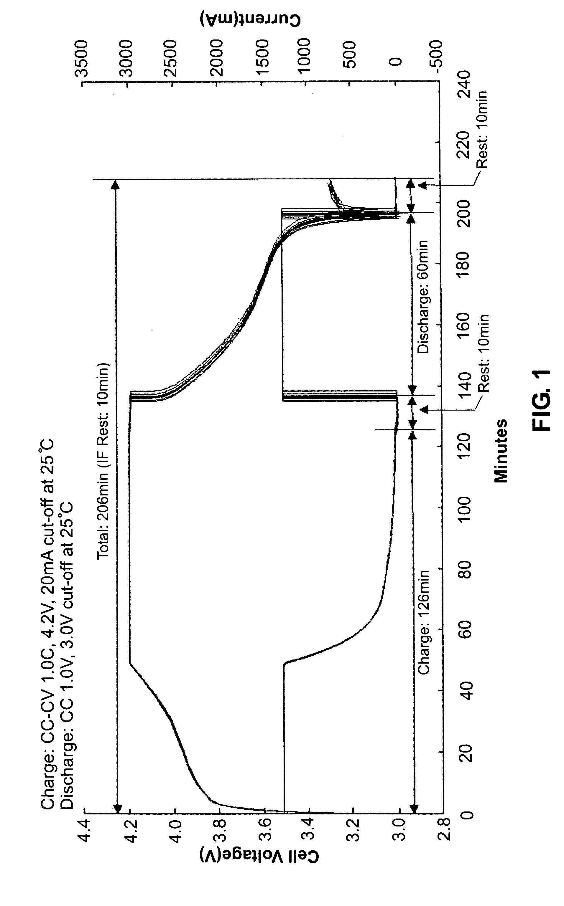
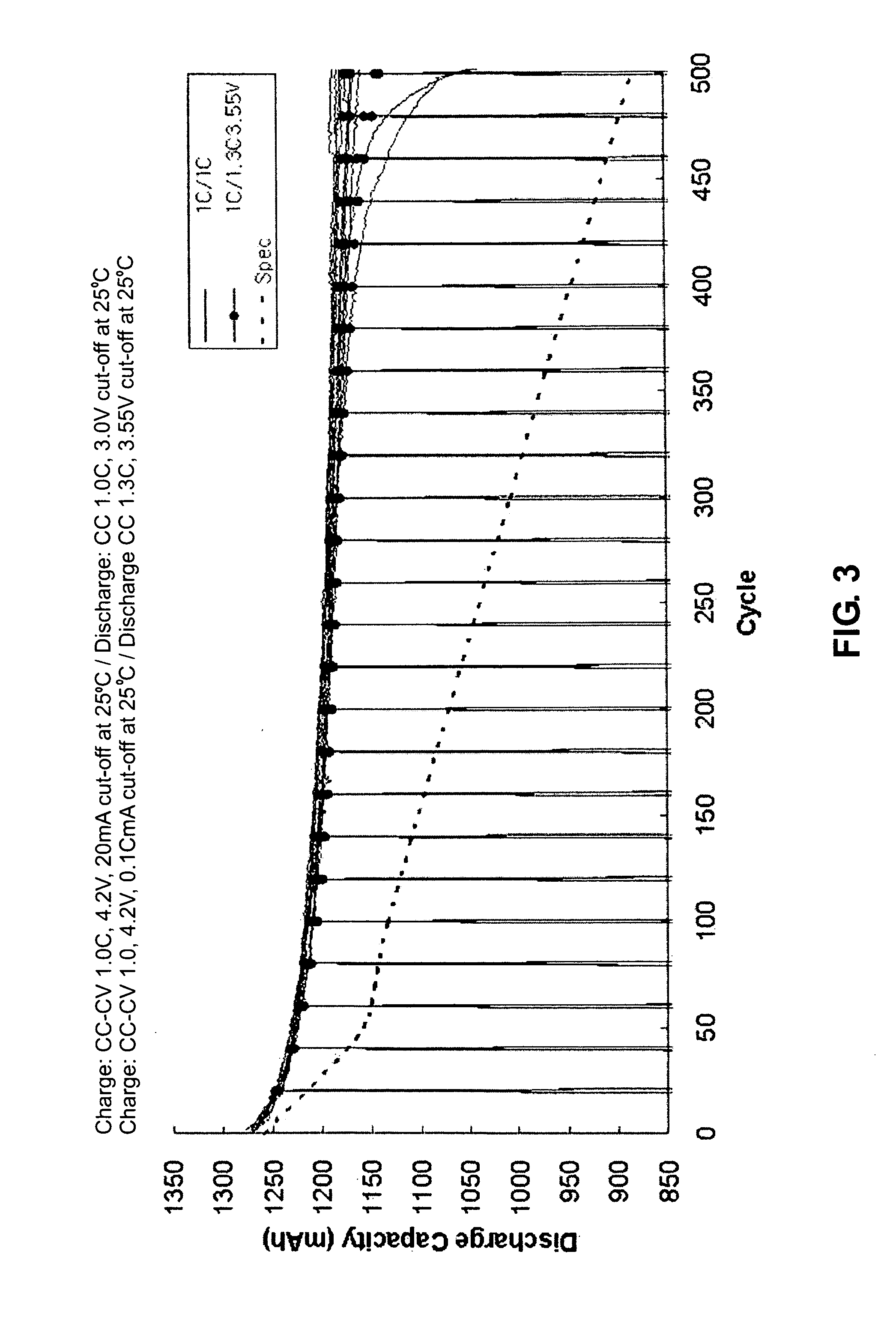
[0057]20 days were required for the cycle life test of 500 cycle at a charge rate of 1.5 C, a charge cut-off current of 0.1 C, and no charge and discharge rest period in the regular charge / discharge method.

embodiment 2

Condition 13 of FIG. 6

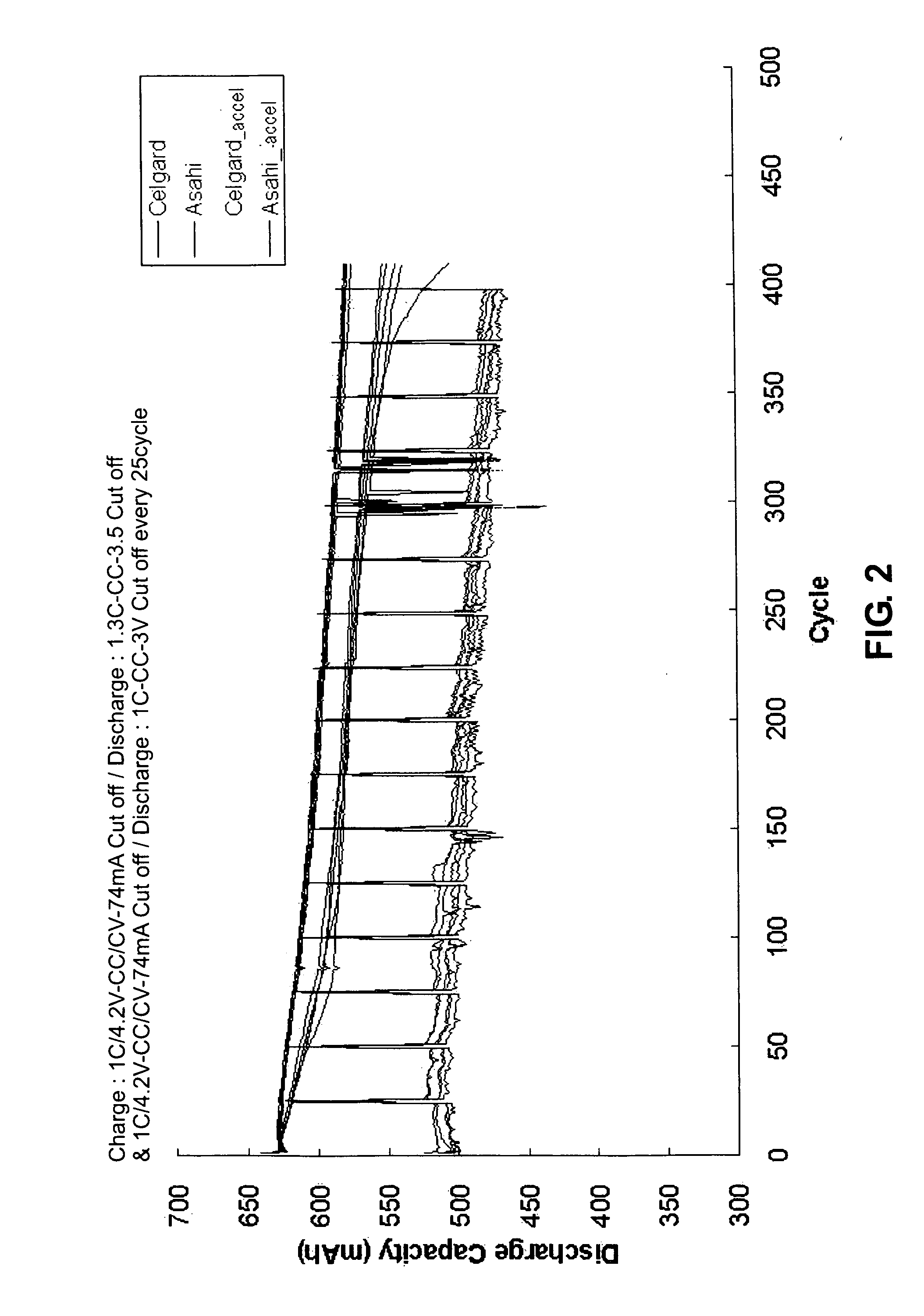
[0066]41 days were required for the cycle life test of 500 cycle at a charge cut-off current of 0.1 C, a discharge rate of 1.3 C, a discharge cut-off voltage of 3.3V, and no charge and discharge rest period in the regular charge / discharge method.

embodiment 3

Condition 14 of FIG. 6

[0070]32 days were required for the cycle life test of 500 cycle at a charge cut-off current of 0.1 C, a discharge rate of 1.3 C, a discharge cut-off voltage of 3.55V, and no charge and discharge rest period in the regular charge / discharge method.


PUM


Abstract

The provided are two test methods for the cycle life test of a lithium rechargeable battery, which measures charge / discharge capacity by repeating charging and discharging lithium rechargeable battery. In one method, a constant current-constant voltage of charge rate of 1.5C and 4.2V, and a cut-off current of 0.1C are set to charge the battery, and a discharge rate of 1.0C and a cut-off voltage of 3.0V are set to discharge the battery, and there is no rest period between the charging and discharging. In another method, a constant current-constant voltage charge condition of charge rate of 1.0C and 4.2V, and a cut-off current of 0.1C are set to charge the battery, and a discharge rate of 1.3C and a cut-off voltage of 3.3V are set to discharge the battery, and there is no rest period between the charging and discharging. The present invention is appropriate to the cycle life test method of 500 cycles.

Description

CLAIM OF PRIORITY[0001]This application makes reference to, incorporates the same herein, and claims all benefits accruing under 35 U.S.C. §119 from an application for METHOD OF TESTING CYCLE LIFE OF LITHIUM RECHARGEABLE BATTERY earlier filed in the Korean Intellectual Property Office on 30 Apr. 2007 and there duly assigned Serial No. 10-2007-0041920.BACKGROUND OF THE INVENTION[0002]1. Field of the Invention[0003]The present invention relates to a method of testing cycle life of lithium rechargeable battery, and more particularly to a method of testing cycle life of lithium rechargeable battery which reduces the time for measuring cycle life.[0004]2. Description of the Related Art[0005]In recent years, rechargeable batteries, which can be charged and discharged, are widely used in mobile electronic / electrical devices. In particular, high-capacity light-weight thin lithium rechargeable battery is being mostly used for lap-top computers, camcorders, mobile phones, and the like, which ...

Claims


Application Information

Patent Timeline
IPC IPC(8): H02J7/00
CPCG01R31/361G01R31/3634G01R31/3648G01R31/3828G01R31/387G01R31/36
Inventor KIM, CHEONSOO
Owner SAMSUNG SDI CO LTD
Learn More