Device and Method for Preparing Filament Yarn of Composite Nanofibers

a technology of composite nanofibers and filament yarns, applied in the direction of filament/thread forming, electric heating, electric/magnetic/electromagnetic heating, etc., can solve the problems of fiber loss and unstable dispersion, difficult to manufacture continuous nanofiber yarns or filaments, and great challenges for the fiber industry

Inactive Publication Date: 2008-10-30
SOUTHEAST UNIV
View PDF12 Cites 46 Cited by
  • Summary
  • Abstract
  • Description
  • Claims
  • Application Information

AI Technical Summary

Benefits of technology

[0012]The present invention has following advantages:
(1) The present invention utilizes a method for preparing filament yarn of composite nanofibers, where electrospinning nozzles oppositely disposed are electrically charged by high DC voltages with opposite polarities. Nanofibers electrospun from the two nozzles which carry charges with opposite polarities attract each other, strike together, and neutralize their charges. The present method shows a less dispersion and loss of nanofibers in the air. Furthermore, grounded metal collector used in conventional electrospinning method is unnecessary in the present invention.
(3) The present invention can manufacture filament yarn of composite nanofibers simply and efficiently.
(4) In the present invention, different polymer solutions or additive-containing polymer solutions can be fed to two spouts of electrospinning nozzles pair oppositely disposed respectively, resulting in the formation of composite filament yarn of multi-component nanofibers.
(5) In the present invention, filament yarn of composite nanofibers with different composition and nano-structure can be produced by the use of multiple pairs of electrospinning nozzles. Thicker multi-layer filament yarn of composite nanofibers may exhibit good mechanical properties.
(6) In the present invention, nanofibers from oppositely disposed electrospinning nozzles which carry charges with opposite polarities can deposit on polymer fiber carrier, and then drawn down by filament guiding roller pair set under frame with a less dispersion or loss of nanofibers. And, multi-layer filament yarn of composite nanofibers with polymer fiber carrier as core is produced having excellent mechanical properties.
(7) The present invention can produce filament yarns of composite nanofibers including nano-particles as combined with electro-spraying technique.
(8) The present invention can manufacture filament yarn of composite nanofibers having potential applications in tissue engineered scaffolds and textiles, etc.

Problems solved by technology

With social development and improvement of people's lives, fiber industry has faced great challenges in recent years as single components could not meet the requirement of fibers with more functions.
However, there exist problems of fiber loss and unstable dispersion due to the nano- / micro-meter size of the electrospun fibers, and repellent force between nanofibers carried charges with same polarity.
It is difficult to manufacture continuous nanofiber yarns or filaments.
Although tremendous progress has been made in the fabrication of aligned nanofibers by electrospinning, a major challenge remains in the search for an efficient means to manufacture continuous aligned filament yarns.

Method used


Image

  • Device and Method for Preparing Filament Yarn of Composite Nanofibers
  • Device and Method for Preparing Filament Yarn of Composite Nanofibers
  • Device and Method for Preparing Filament Yarn of Composite Nanofibers

Examples


example 1

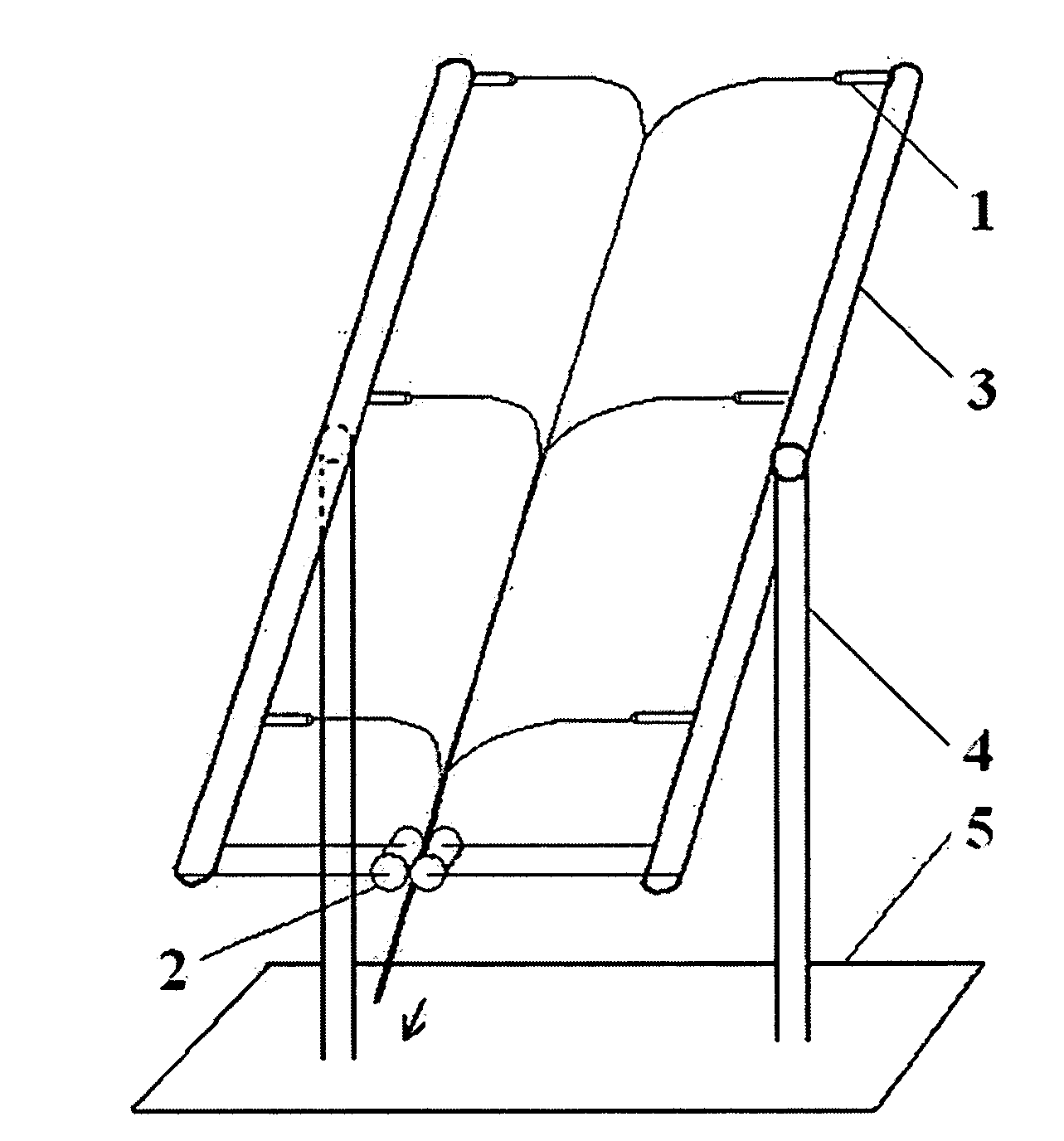
[0028]A device for electrospinning is used comprising frame 3 having three pairs of electrospinning nozzles 1 in two columns, filament guiding roller pair 2 set at the end of pairs of electrospinning nozzles. The frame 3 was set at angle of 90° to fixed sticks 4.

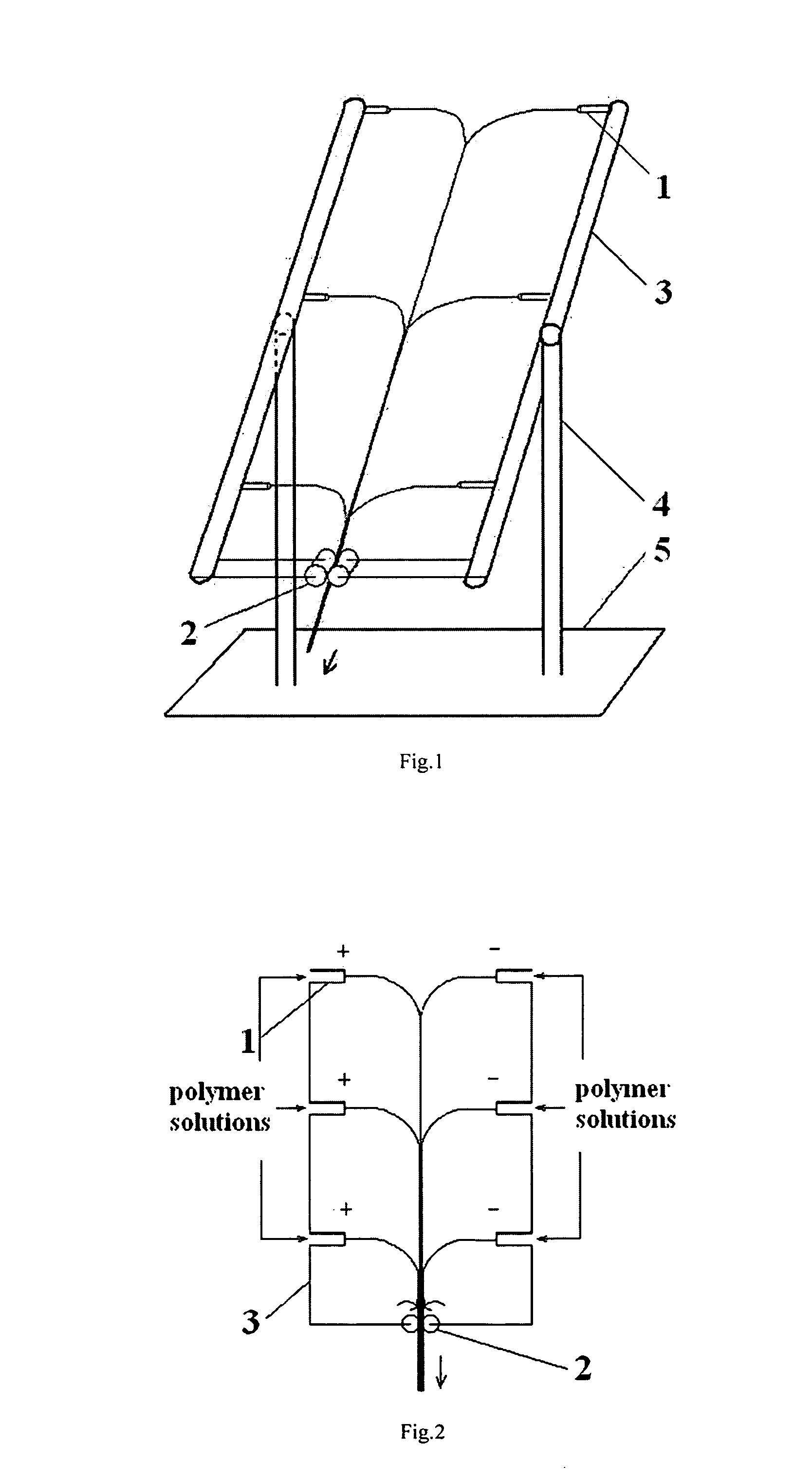
[0029]10 g poly-L-lactic acid (PLLA, Mη=100,000 g / mol) was dissolved in a mixed solvent of 50 ml acetone and 50 ml N,N-dimethyl formamide, and the prepared solution was fed to one column of electrospinning nozzles containing 3 spinnerets. 15 g poly-lactide-co-glycolide (Poly-LA-co-GA, PLGA, weight ratio of LA:GA=50:50, Mη=100,000 g / mol) was dissolved in a mixed solvent of 50 ml acetone and 50 ml N,N-dimethyl formamide, and the prepared solution was fed to the other column of electrospinning nozzles containing 3 spinnerets. Distance between two neighbouring electrospinning nozzles on the same column of frame 3 is 15 cm, and distance between two tips of oppositely disposed pair of electrospinning nozzles is 40 cm. Plane of fra...

example 2

[0030]A device for electrospinning is used comprising frame 3 having four pairs of electrospinning nozzles 1 in two columns, filament guiding roller pair 2 set at the end of pairs of electrospinning nozzles. The frame 3 was set at angle of 90° to fixed sticks 4.

[0031]10 g poly-L-lactic acid (PLLA, Mq=100,000 g / mol) was dissolved in a mixed solvent of 50 ml acetone and 50 ml N,N-dimethyl formamide, and the prepared solution was fed to one column of electrospinning nozzles containing 4 spinnerets. 10 g polycaprolactone (PCL, Mw=90,000 g / mol) was dissolved in 100 ml N, N-dimethyl formamide, and the prepared solution was fed to the other column of electrospinning nozzles containing 4 spinnerets. Distance between two neighbouring electrospinning nozzles on the same column of frame 3 is 15 cm, and distance between two tips of oppositely disposed pair of electrospinning nozzles is 40 cm. Plane of frame 3 is set at angle of 90° to fixed sticks 4. High DC voltages of ±20 kV were applied to t...

example 3

[0032]A device for electrospinning is used comprising frame 3 having three pairs of electrospinning nozzles 1 in two columns, filament guiding roller pair 2 set at the end of pairs of electrospinning nozzles. The frame 3 was set at angle of 90° to fixed sticks 4.

[0033]10 g poly-L-lactic acid (PLLA, Mη=100,000 g / mol) was dissolved in a mixed solvent of 50 ml acetone and 50 ml N,N-dimethyl formamide, and the prepared solution was fed to one column of electrospinning nozzles containing 3 spinnerets of which inner diameter is 0.8 mm. 35 g zein (Mw=35,000 g / mol) was dissolved in 100 ml aqueous ethanol solution with ethanol / water volume ratio of 80 / 20, and the prepared solution was fed to the other column of electrospinning nozzles containing 3 spinnerets of which inner diameter is 1.2 mm. Distance between two neighbouring electrospinning nozzles on the same column of frame is 15 cm, and distance between two tips of oppositely disposed pair of electrospinning nozzles is 40 cm. Plane of fr...


PUM

PropertyMeasurementUnit
Electric potential / voltageaaaaaaaaaa
Distanceaaaaaaaaaa
Distanceaaaaaaaaaa

Abstract

Device and method for preparing filament yarn of composite nanofibers. The device includes pairs of electrospinning nozzles on a frame and filament guiding roller pair under the frame. The spouts of each pair of nozzles are oppositely facing. The method includes feeding polymer solutions to the pairs of nozzles, applying high DC voltage with opposite polarity respectively to each one of the pairs of nozzles, forming composite nanofibers by attracting nanofibers with opposite charge from each nozzle and striking together of the charged nanofibers, pulling / stretching the composite nanofibers to form filament yarn of composite nanofibers, drawing down the filament yarn of composite nanofibers from the first pair of nozzles and using it as a carrier to receive the nanofibers with opposite charge electrospun from the second pair of nozzles and coated by the same so as to form multi-layer (e.g., two- or more-layer) filament yarn of composite nanofibers.

Description

CROSS-REFERENCE TO RELATED APPLICATION(S)[0001]is application is a National Phase Patent Application and claims the priority of International Application Number PCT / CN2006 / 003014, filed on Nov. 10, 2006, which claims priority of Chinese Patent Application Number 200610095384.0, filed on Jan. 11, 2006.FIELD OF THE TECHNOLOGY[0002]The present invention relates to device and method for preparing filament yarn of composite nanofibers. It belongs to the technical field of manufacturing special fibers.BACKGROUND OF THE INVENTION[0003]With social development and improvement of people's lives, fiber industry has faced great challenges in recent years as single components could not meet the requirement of fibers with more functions. Various types of composite fibers have been developed, such as core-sheath, filling, bilateral, sea-island and other types of composite fibers. US Patent (No. 4,717,325) designed a spinneret assembly with composite feed plates. Passages are aligned with the orifi...

Claims


Application Information

Patent Timeline
IPC IPC(8): D01D5/00
CPCD01D5/0061D01F8/00
Inventor LI, XINSONGYAO, CHENSUN, FUQIAN
Owner SOUTHEAST UNIV
Why Eureka
Try Eureka