Hypoid gear motor and method of producing hypoid gear motor

Inactive Publication Date: 2008-10-30
SUMITOMO HEAVY IND LTD
View PDF10 Cites 18 Cited by
  • Summary
  • Abstract
  • Description
  • Claims
  • Application Information

AI Technical Summary

Benefits of technology

[0015]Another and more specific object of the present invention is to provide a hypoid gear motor having a structure suited for a design with a high capacity and a low reduction gear ratio (or a high-speed drive) while minimizing the size of the hypoid gear motor, and to a method of producing such a hypoid gear motor.
[0016]According to one aspect of the present invention, there is provided a hypoid gear motor comprising a casing; a first bearing; a second bearing; a motor having a motor shaft; a hypoid pinion having a penetration hole, and a tooth flank on an outer periphery thereof, the hypoid pinion being separate from the motor shaft and being fixed to the motor shaft which is fitted into the penetration hole; a hypoid gear shaft having a hypoid gear which meshes with the hypoid pinion, and two ends respectively supported on the casing via the first and second bearings; a first shim member arranged adjacent to the first bearing; and a second shim member arranged adjacent to the second bearing, wherein the first and second shim members independently adjust a position of the hypoid gear shaft in an axial direction thereof with respect to the hypoid pinion and the casing. In this case, it is possible to realize a hypoid gear motor having a structure suited for a design with a high capacity and a low reduction gear ratio (or a high-speed drive) while minimizing the size of the hypoid gear motor.
[0017]According to another aspect of the present invention, there is provide a hypoid gear motor comprising a gear casing; a first bearing part; a second bearing part; a motor having a motor shaft; a hypoid pinion having a penetration hole, and a tooth flank on an outer periphery thereof, the hypoid pinion being fixed to the motor shaft which is fitted into the penetration hole; a hypoid gear shaft having a hypoid gear which meshes with the hypoid pinion, and two ends respectively supported on the gear casing via the first and second bearing parts, wherein a position of the hypoid gear shaft in an axial direction thereof with respect to the hypoid pinion and the gear casing is independently adjustable by the first and second bearing parts. In this case, it is possible to realize a hypoid gear motor having a structure suited for a design with a high capacity and a low reduction gear ratio (or high-speed drive) while minimizing the size of the hypoid gear motor.
[0018]According to still another aspect of the present invention, there is provided a method of producing a hypoid gear motor, comprising the steps of fixing a motor shaft of a motor to a hypoid pinion by fitting the motor shaft into a penetration hole in the hypoid pinion; assembling a hypoid gear shaft having a hypoid gear into the hypoid gear motor while adjusting meshing positions of the hypoid gear and the hypoid pinion using a first shim member which is arranged adjacent to a first bearing supporting one end of the hypoid gear shaft; and adjusting relative positions of the hypoid gear shaft and a gear casing in an axial direction using a second shim member which is arranged adjacent to a second bearing supporting another end of the hypoid gear shaft. In this case, it is possible to realize a hypoid gear motor having a structure suited for a design with a high capacity and a low reduction gear ratio (or high-speed drive) while minimizing the size of the hypoid gear motor.

Problems solved by technology

When a relatively low gear ratio is realized by use of a motor having a certain capacity, an output torque of the output shaft naturally becomes small.
For example, if the high-speed drive were to be realized by maintaining the same torque in an existing production facility, there is a problem in that it would be necessary to make design modifications of the connecting dimensions or linkage mechanisms of the reduction gear casing and the like with respect to the production facility.

Method used


Image

  • Hypoid gear motor and method of producing hypoid gear motor
  • Hypoid gear motor and method of producing hypoid gear motor
  • Hypoid gear motor and method of producing hypoid gear motor

Examples


Embodiment Construction

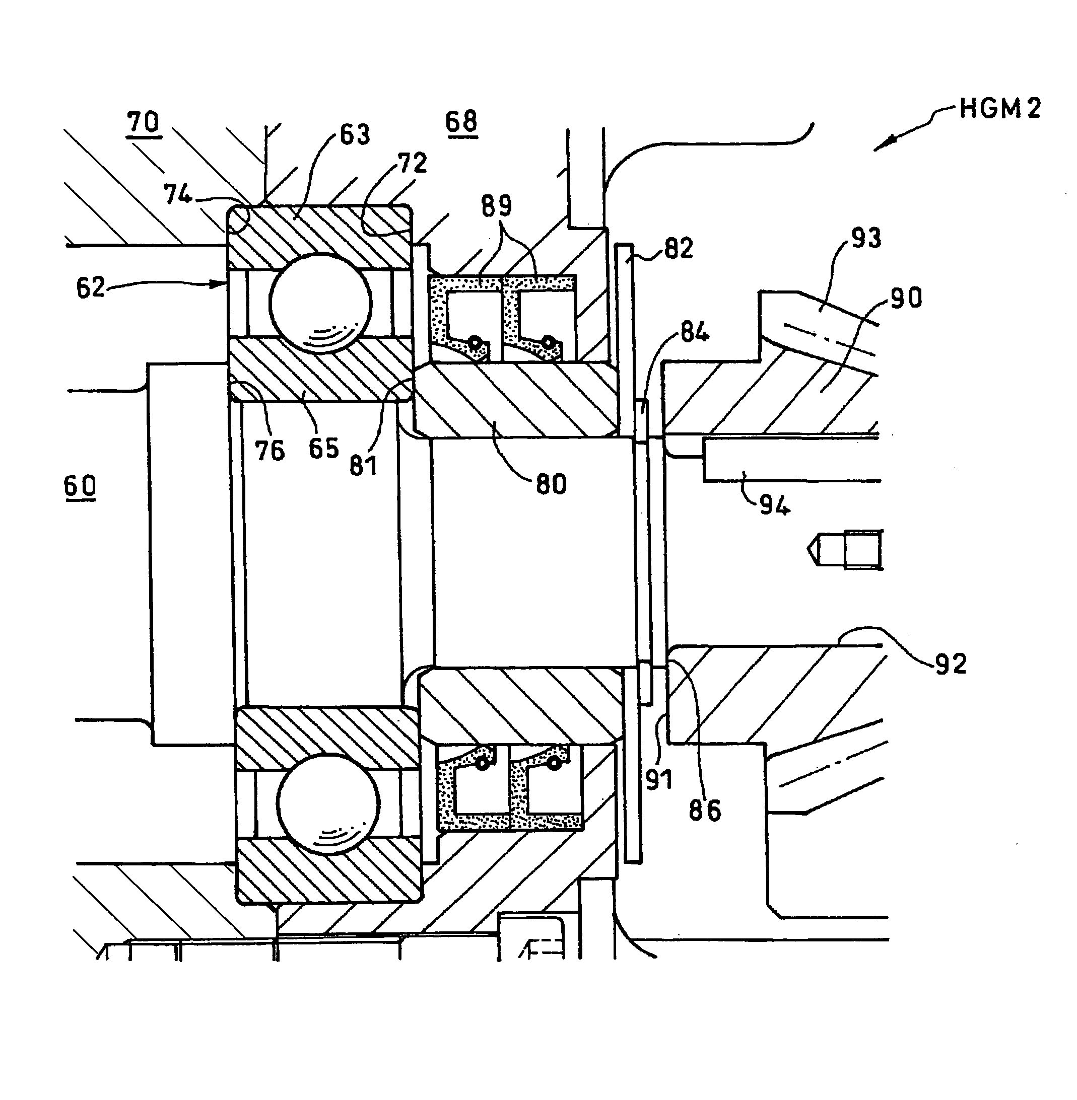
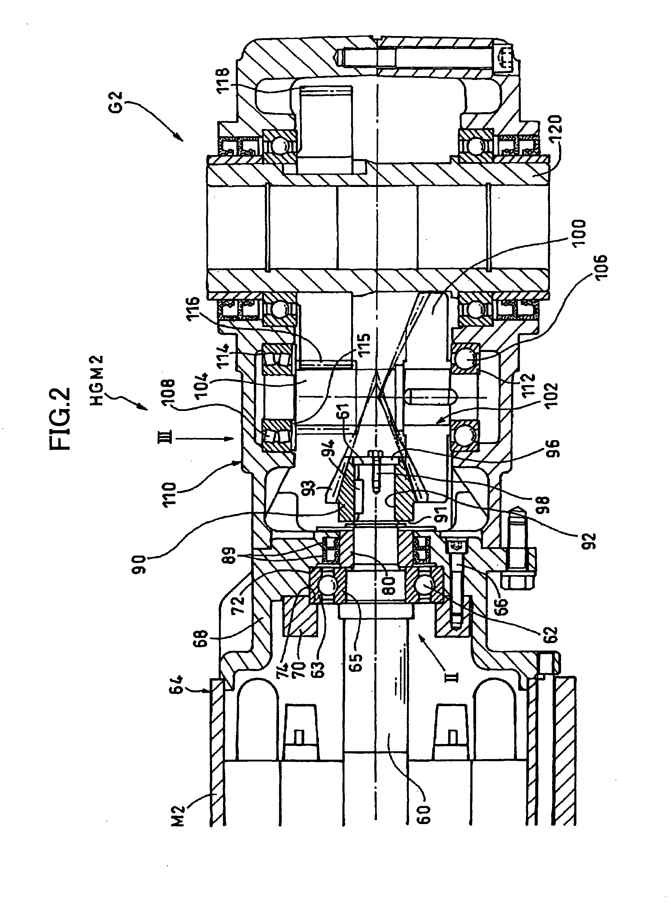
[0027]In one embodiment of the present invention, a hypoid gear motor has a gear casing, a first bearing, a second bearing, a motor having a motor shaft, a hypoid pinion having a penetration hole and a tooth flank on an outer periphery thereof, and being separate from the motor shaft and fixed to the motor shaft which is fitted into the penetration hole, a hypoid gear shaft having a hypoid gear which meshes with the hypoid pinion and two ends respectively supported on the gear casing via the first and second bearings, a first shim member arranged adjacent to the first bearing, and a second shim member arranged adjacent to the second bearing. The first and second shim members independently adjust a position of the hypoid gear shaft in an axial direction thereof with respect to the hypoid pinion and the gear casing.

[0028]One embodiment of the present invention does not rely on the conventional concept of realizing a suitable reduction gear ratio of approximately 1 / 5 to approximately 1...


PUM


Abstract

A hypoid gear motor has a gear casing, first and second bearings, a motor having a motor shaft, a hypoid pinion having a penetration hole and a tooth flank on an outer periphery thereof, with the motor shaft fitted into the penetration hole, a hypoid gear shaft having a hypoid gear which meshes with the hypoid pinion, and two ends respectively supported on the gear casing via the first and second bearings, and first and second shim members arranged adjacent to the first and second bearings, respectively. The first and second shim members independently adjust a position of the hypoid gear shaft in an axial direction thereof with respect to the hypoid pinion and the gear casing.

Description

BACKGROUND OF THE INVENTION[0001]1. Field of the Invention[0002]The present invention generally relates to hypoid gear motors and methods of producing hypoid gear motors, and more particularly to a hypoid gear motor having a structure suited for a design with a high capacity and a low reduction gear ratio and to a method of producing such a hypoid gear motor.[0003]2. Description of the Related Art[0004]For example, a Japanese Laid-Open Patent Application No. 2001-103710 proposes a hypoid gear motor for realizing a wide range of reduction gear ratios, from a low reduction gear ratio to a high reduction gear ratio.[0005]FIG. 1 is a cross sectional view showing an example of a conventional hypoid gear motor, namely, the hypoid gear motor proposed in the Japanese Laid-Open Patent Application No. 2001-103710. A hypoid gear motor HGM1 shown in FIG. 1 integrally has a motor M1 and a reduction gear G1.[0006]A first gear stage of the reduction gear G1 is formed by a hypoid pinion 16 directly...

Claims


Application Information

Patent Timeline
IPC IPC(8): F16H57/02F16C23/08F16H1/14F16H57/021F16H57/022H02K7/116
CPCF16H1/145Y10T74/2186F16H57/022
Inventor MINESHIMA, YASUSHI
Owner SUMITOMO HEAVY IND LTD
Why Eureka
Try Eureka