Interferometry system chamber viewing window

Inactive Publication Date: 2008-10-23
THE AEROSPACE CORPORATION
View PDF2 Cites 10 Cited by
  • Summary
  • Abstract
  • Description
  • Claims
  • Application Information

AI Technical Summary

Benefits of technology

[0011]Still another object of the invention is to provide a viewing window having a rigidly embedded optical beam splitter and attached reference mirror for canceling out phase differences between a reference beam and an object beam.
[0019]An interferometry system can resolve longitudinal distances on sub-nanometer scales. This extreme sensitivity also means that the system is incredibly sensitive to air currents, sonic vibration, and other sources of noise present in the lab environment. By incorporating the interferometer optical paths into a single rigid body, the effects of vibration are attenuated even further. The system enables practical and routine laboratory interferometry use. The system provides improved immunity to noise with mobility and accessibility. By integrating the interferometric components into a single device, all of the optical alignment can be done during fabrication. The system can be easily used for making high optical alignments with very high-resolution measurements. These and other advantages will become more apparent from the following detailed description of the preferred embodiment.

Problems solved by technology

The harsh environment and stringent reliability requirements of space technology require detailed knowledge of the motion of all mechanical devices.
These inferential results are unacceptable for the requirements of modern aerospace applications and are often lacking in their precision when related to dynamic operation.
To study the motion of microscopic mechanical parts, it is not practical to load them with sensors.
These products, however, have serious drawbacks.
In addition to this failing, the vibrometer measures single points at a time, requiring accurate scanning and stitching over the entire surface of the test object.
The actual motion and shape of the device must then be gained inferentially through analysis and is subject to many sources of error, both in the scanning and interpretation of device measurements.
The white light interferometer has similar problems.
While this does generate displacement data over a large dynamic range, the long scan time relies on very highly repeated motion.
Couple this requirement to a slightly noisy environment and the data becomes riddled with potential errors.
The second objective puts even further constraints on the allowed displacement tolerances.
This creates a very difficult problem in calibrating the system.
Achieving such precision is not practical in a manufacturing or testing environment.
In a conventional interferometer, vibration in any part of either optical path, that is, in the microscope objective path, reference mirror path, or at the device, is translated into measurement errors.
This presents a serious obstacle to high fidelity metrology.
Currently, these types of microscopic interferometers disadvantageously require floating optical tables and controlled laboratory environments.

Method used


Image

  • Interferometry system chamber viewing window
  • Interferometry system chamber viewing window
  • Interferometry system chamber viewing window

Examples


Embodiment Construction

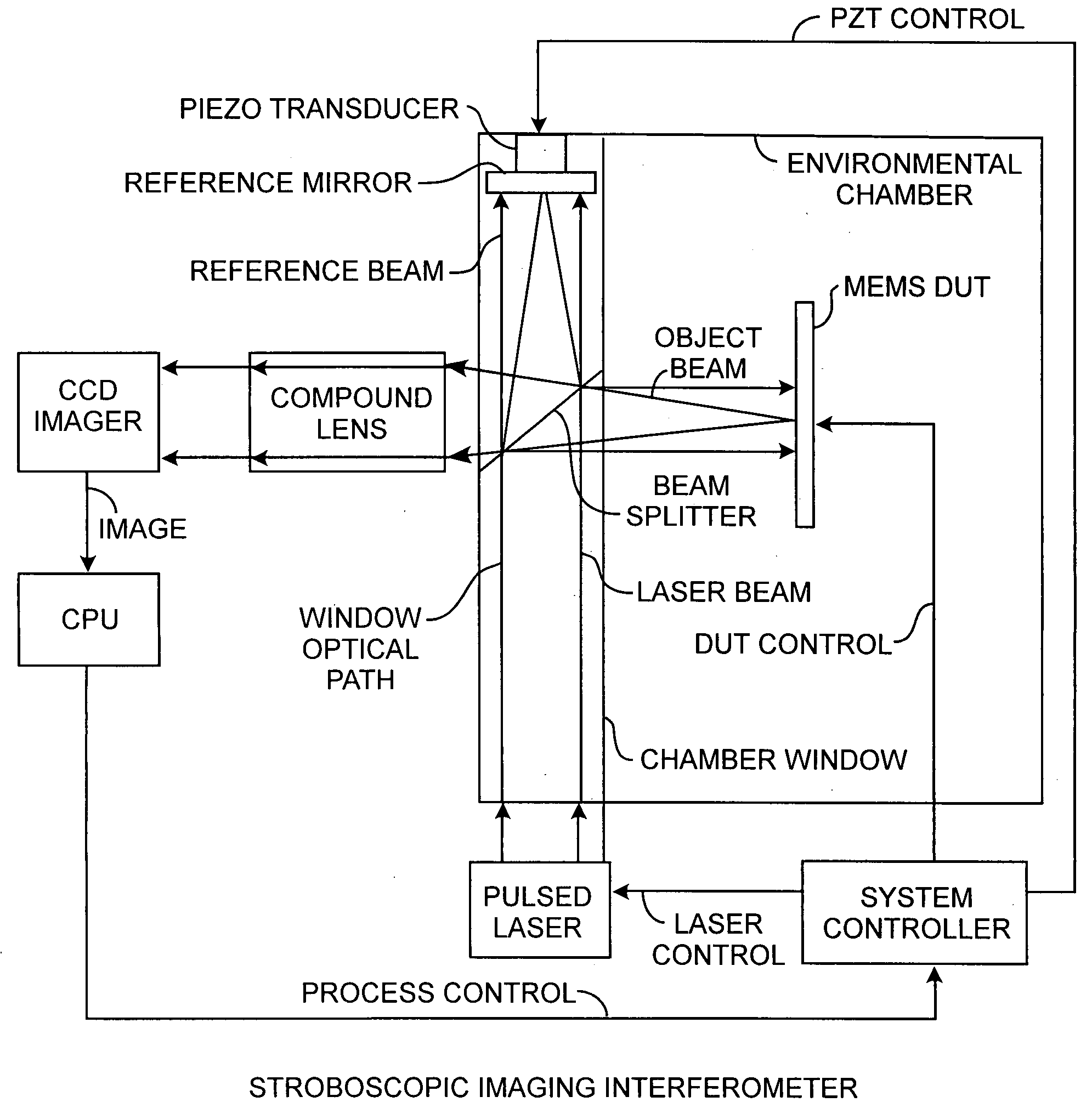
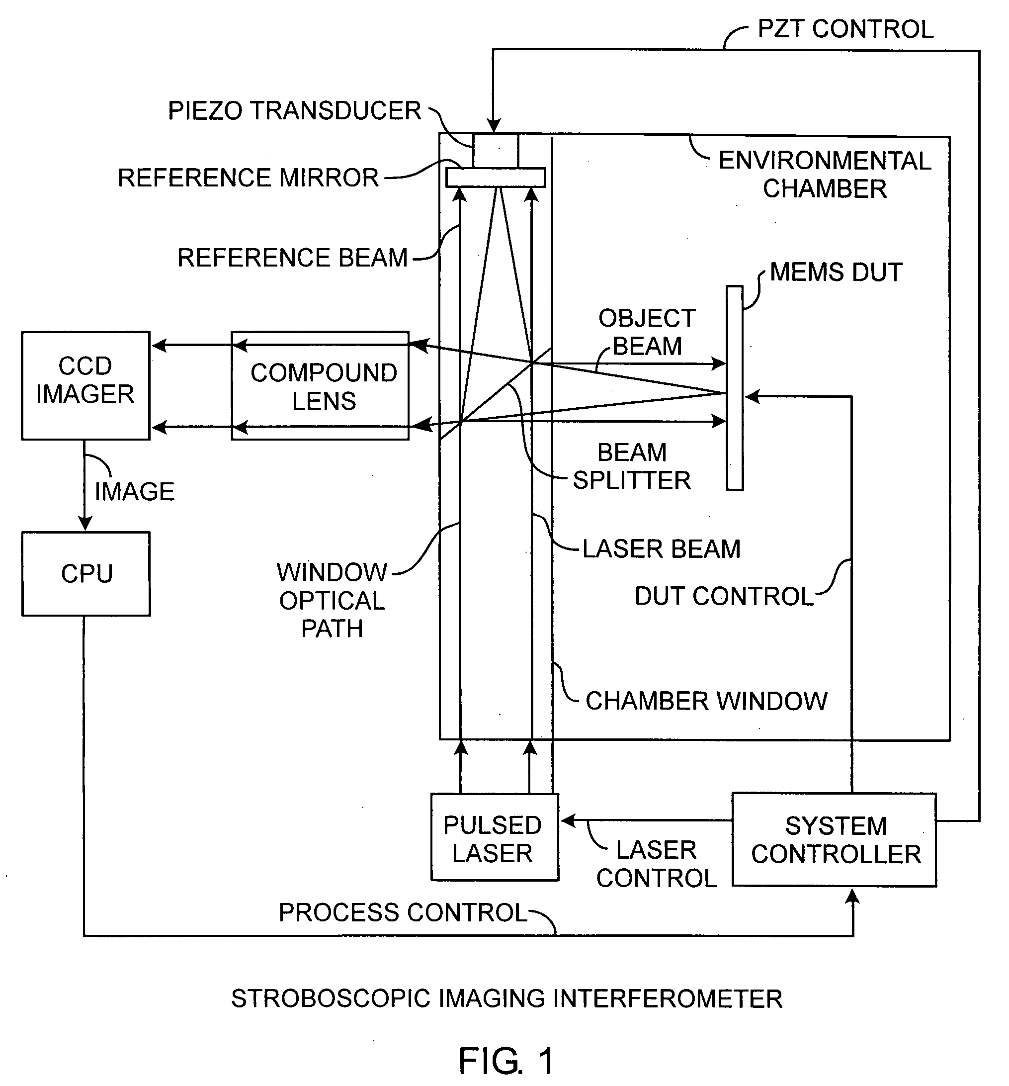
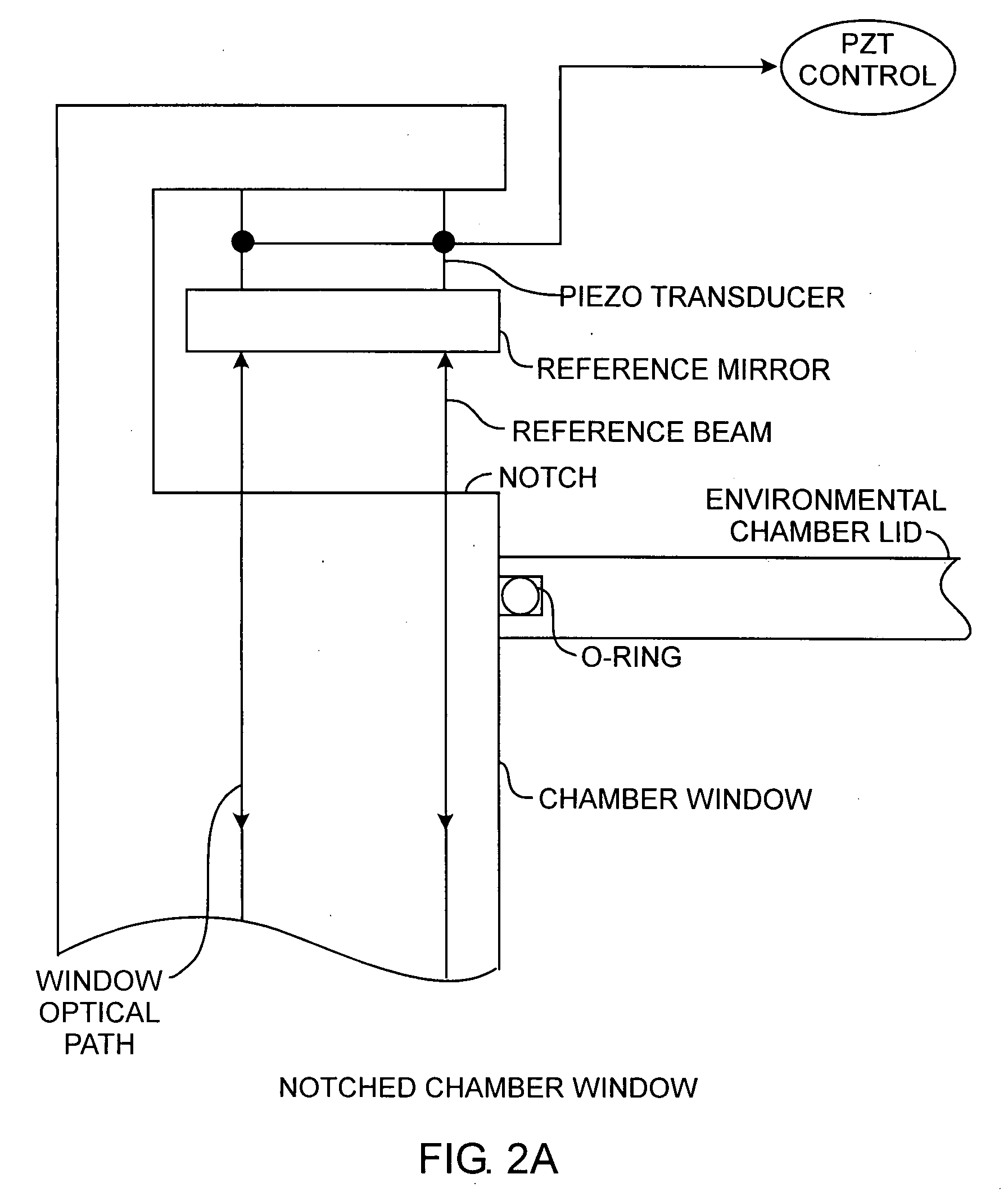
[0025]An embodiment of the invention is described with reference to the figures using reference designations as shown in the figures. Referring to FIG. 1, a pulsed laser emits a laser beam along a window optical path in a chamber window toward a splitter disposed in the chamber window of an environmental chamber. The splitter passes a portion of the laser beam as a reference beam toward a reference mirror and reflects another portion of the laser beam as an object beam toward a device under test (DUT) that may be a MEMS device. The DUT reflects the object beam back through the splitter and out the chamber window toward an objective lens that may be a compound lens. The phase of reference beam relative to that of the object beam is adjusted by actuation of a Piezo transducer (PZT). As the object beam passes through the splitter, the reference beam reflected off the reference mirror interferes with the object beam, creating an interference pattern. The object beam passes through the c...


PUM


Abstract

A stroboscopic imaging interferometer system includes an environmental chamber having a novel viewing window equipped with a rigidly integrated beam splitter and piezo actuated reference mirror for illuminating a device providing an object beam and reference mirror for providing a reference beam, upon the reflection of both beams, produces interference of the object beam by the reference beam for providing absolute phase observations of the device, that may be a MEMS device under test.

Description

STATEMENT OF GOVERNMENT INTEREST[0001]The invention was made with Government support under contract No. FA8802-04-C-0001 by the Department of the Air Force. The Government has certain rights in the invention.FIELD OF THE INVENTION[0002]The invention relates to the field of interferometry. More particularly, the present invention relates to the viewing port of interferometry chambers for measuring surfaces of a device under inspection by an interferometry system.BACKGROUND OF THE INVENTION[0003]The harsh environment and stringent reliability requirements of space technology require detailed knowledge of the motion of all mechanical devices. The failure modes must be well understood and catalogued. While this may be a straightforward analysis for macroscopic devices, microscopic mechanical structures require new tools to study their response under various conditions. In the existing art, static methods are generally employed and the motion of micro-electromechanical systems (MEMS) is ...

Claims


Application Information

Patent Timeline
IPC IPC(8): G01B11/00
CPCB81C99/005G01B9/02052G01B9/02049G01B9/02014
Inventor OSBORN, JON V.CONWAY, JOSH A.FOWLER, JESSE D.
Owner THE AEROSPACE CORPORATION
Why Eureka
Try Eureka