
Fire alarm system

a technology of fire alarm system and fire alarm, which is applied in the direction of fire alarm, smoke/gas actuation, fire alarm, etc., can solve the problems of not providing detailed information to the occupants, such evacuation routes or instructions, and a large amount of frequently changing occupants, and achieves cost-effective effects

Inactive Publication Date: 2008-10-23
MOSS J DARRYL
View PDF25 Cites 28 Cited by
  • Summary
  • Abstract
  • Description
  • Claims
  • Application Information

AI Technical Summary

Benefits of technology

[0049]One advantage of the invention is that an addressable 120 volt detector not only alerts the tenant when something was wrong, but also alerts the building owner / security.
[0050]Another advantage of the invention is that it allows a high voltage contractor and a low voltage contractor to merge the two systems together, providing the owner / end user a cost effective solution in residential fire alarm system applications where both tenants and building owner / security office can respond to an emergency faster, knowing precisely which unit has detected a trouble condition.

Problems solved by technology

The rationale behind audio evacuation systems is, though conventional fire alarm notification devices alert occupants of a building of the presence of an emergency, they do not provide detailed information to the occupants, such evacuation routes or instructions.
The problem lies in buildings where there are a large amount of frequently changing occupants who are not necessarily familiar with the locations of emergency exits or stairwells.
This could result in no one in the building knowing that the unit is burning, especially if the tenant isn't home, until the smoke / heat from the unit eventually billows from underneath the door leading to the building core and activates the building alarm system.

Method used


Image

  • Fire alarm system
  • Fire alarm system
  • Fire alarm system

Examples


Embodiment Construction

[0056]The present invention will now be described in detail with reference to at least one preferred embodiment thereof as illustrated in the accompanying drawings. In the following description, numerous specific details are set forth in order to provide a thorough understanding of the present invention. It will be apparent, however, to one skilled in the art, that the present invention may be practiced without some or all of these specific details. In other instances, well known operations have not been described in detail so not to unnecessarily obscure the present invention.

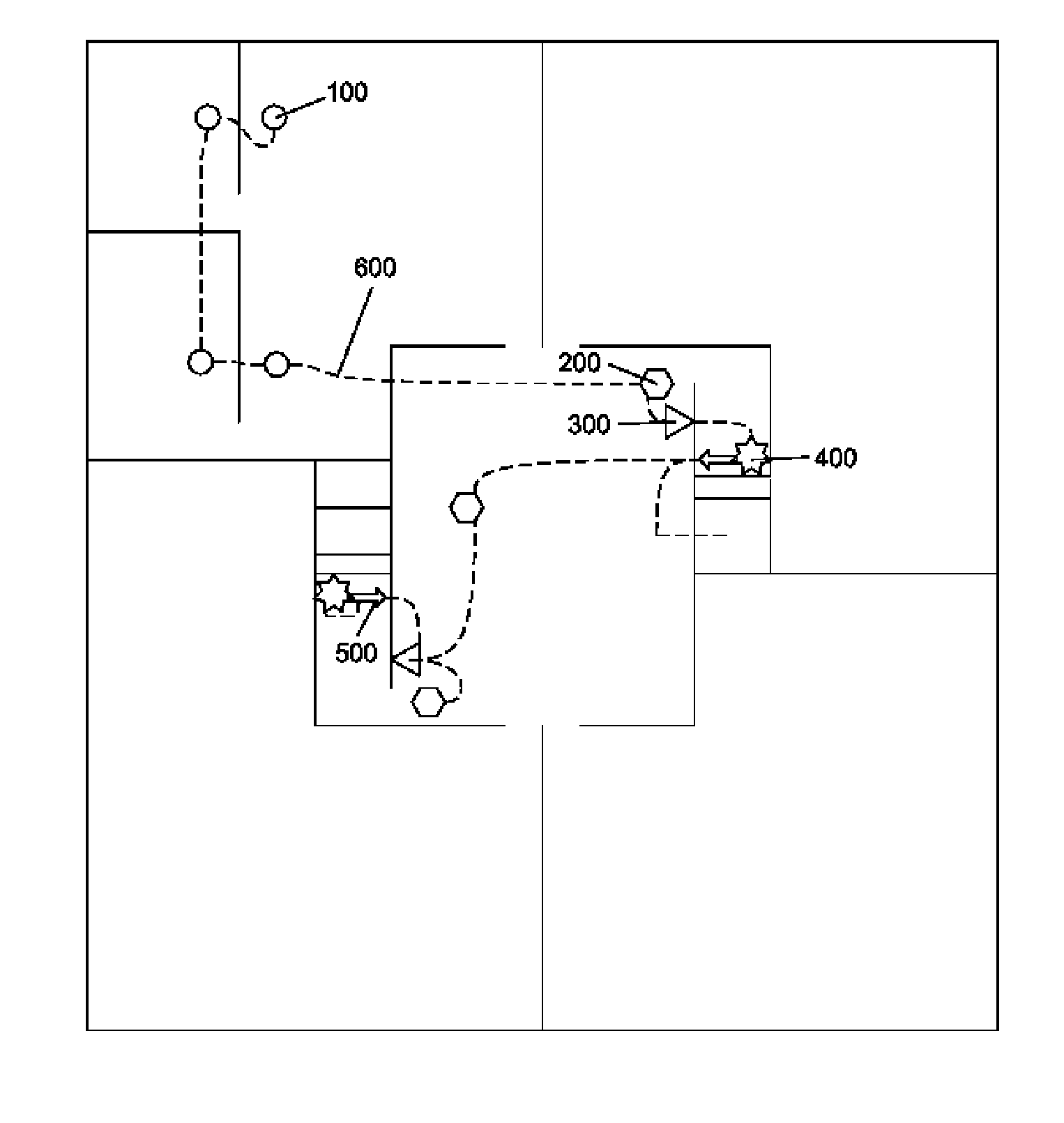
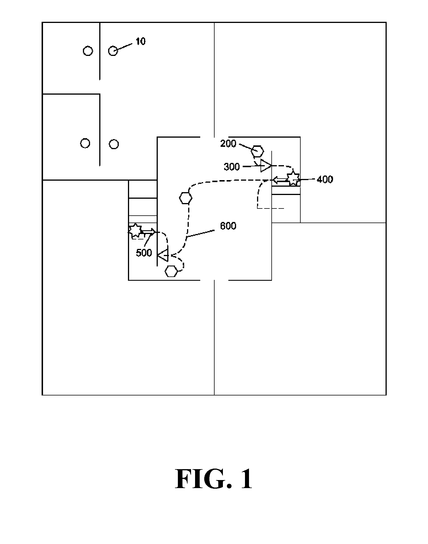
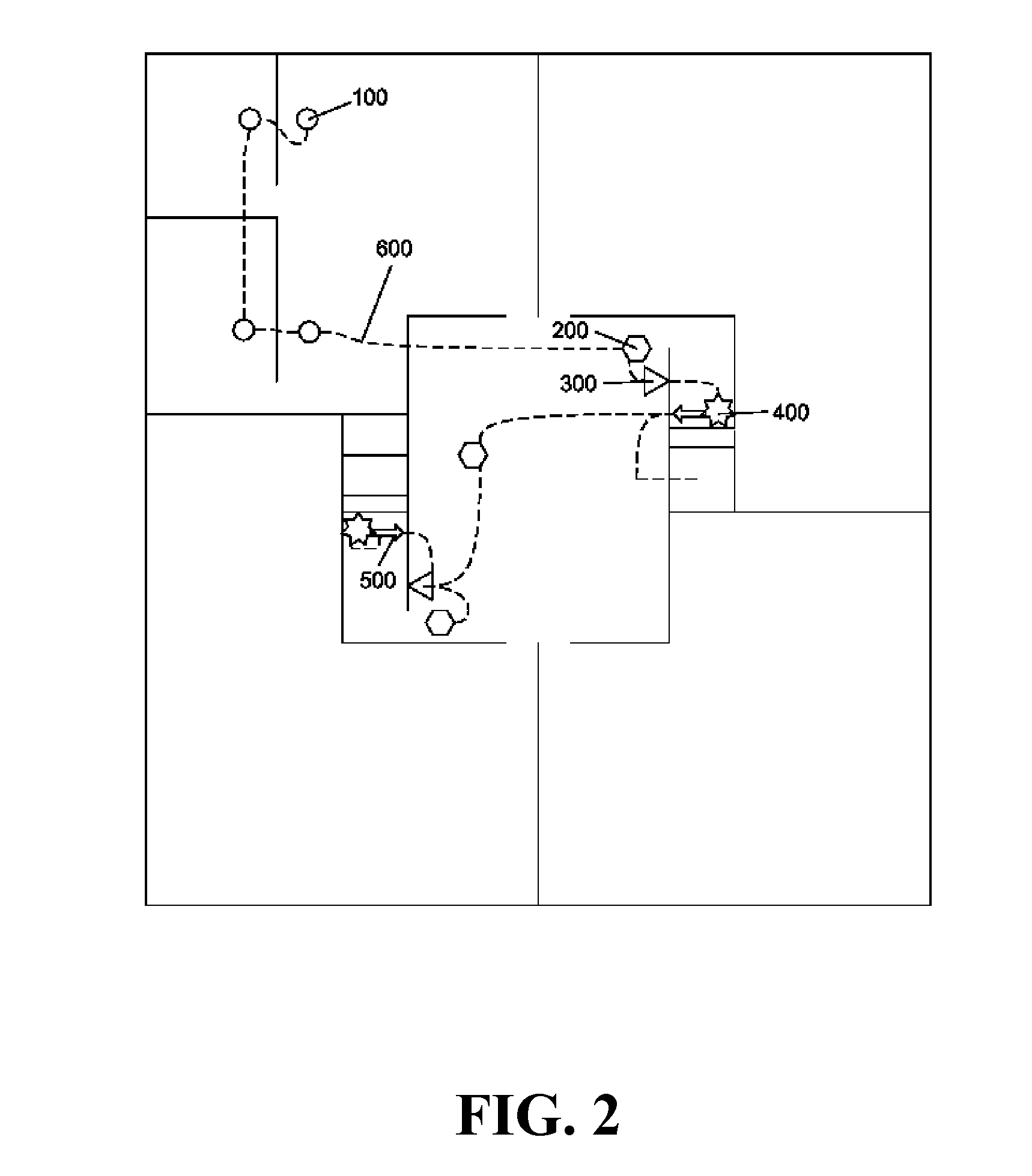
[0057]Referring to the drawings wherein like reference numerals designate corresponding parts throughout the several figures, reference is made first to FIG. 1 that illustrates a typical fire alarm system for a floor in a high rise condo building.

[0058]In FIG. 1, four of a 120 volt non-addressable smoke detector 10 is represented as deployed within a unit of a floor. The 120 volt non-addressable smoke detector...


PUM


Abstract

A fire alarm system is disclosed where the unit detectors are addressable and in communication with other unit detectors located within a particular unit and are in communication with building detectors such that when one unit detector activates, all the other unit detectors in that unit also activate causing communication with the building core detectors and alerting the control room as to the exact location of the alarm condition.

Description

FIELD OF THE INVENTION[0001]The present invention relates generally to fire alarm systems, and more particularly to a fire alarm system for commercial and residential structures.BACKGROUND OF THE INVENTION[0002]The invention pertains in general to fire alarm systems, and in particular to a fire alarm system employing a 120 volt ionization / photoelectric smoke / heat detector with an addressable dip switch, or equivalents thereof.[0003]With fire alarm systems, the design of the overall goals, general system type, and integration into the other facility systems (active fire suppression, HVAC, lighting, electrical power, fire barriers, etc.) is performed by competent engineers with experience in fire protection, who are licensed within the geographical area of practice, such as a U.S., State or a Canadian Province. This is done in conjunction with the Architect's design team during the design phase of the building project. The detailed component selection and layout is provided by a techn...

Claims


Application Information

Patent Timeline
IPC IPC(8): G08B25/00
CPCG08B17/10G08B25/009G08B25/14
Inventor MOSS, J. DARRYL
Owner MOSS J DARRYL
Learn More