
Device

a technology of a device and a clamping plate, which is applied in the direction of machine supports, building scaffolds, domestic objects, etc., can solve the problems of pipelines being susceptible to compression and creep of insulation coatings, low friction coefficient of the inner tube of the riser, and relatively delica

Inactive Publication Date: 2008-10-16
BALMORAL COMTEC
View PDF15 Cites 21 Cited by
  • Summary
  • Abstract
  • Description
  • Claims
  • Application Information

AI Technical Summary

Benefits of technology

[0017]The elastomer hinge allows the clamp frame to be hinged open when mounting on a riser which ensures that the alignment of the segments is maintained during the mounting operation.
[0021]Advantageously the jacket covers the upper and lower regions of the outer face of the frame whilst leaving the centre region uncovered. This provides a recess for the tensioning band to surround the frame without having to form a recess into the body of the frame to locate the band.

Problems solved by technology

This sheathing has a low coefficient of friction with the inner tube of the riser and so is relatively delicate.
Such pipelines are susceptible to compression and creep of the insulation coatings which are applied to the outer surface of the risers.
However the attachment of the clamp must be done carefully since the sheath on the riser is liable to tear away from the underlying tensile layers of the riser if attachments thereto are over-tensioned.
It is possible to make a rigid bodied clamp that is a perfect fit on a riser (the very earliest clamps were individually bored from aluminium castings to match particular locations on a riser) but it is expensive and not very practical as actual diameter of a flexible riser in practice can easily exceed + / −3% of a given diameter.
In any case, the changes in internal and external pressure and temperature of the riser can result in a variance in the diameter of the riser and affect its connection to a clamp.
Moreover the bending and strains which occur in risers in use further hinder the correct dimensioning of rigid clamps.
As a result manufacturing clamps with an exact fit for the flowlines was difficult and expensive and such clamps were in any case subject to failure due to the in situ variance in riser diameter.
Although somewhat satisfactory, performance limitations are constantly being challenged with demands for clamps to cope with larger buoyancy loads and deployment in rougher sea states, and to accommodate larger riser strains and tighter riser bend radii and high rates of change of these radii.
However, increasing the load capacity is limited by the low coefficient of friction between the outer sheath of the riser and the tensile layers.

Method used


Image

  • Device
  • Device
  • Device

Examples


Embodiment Construction

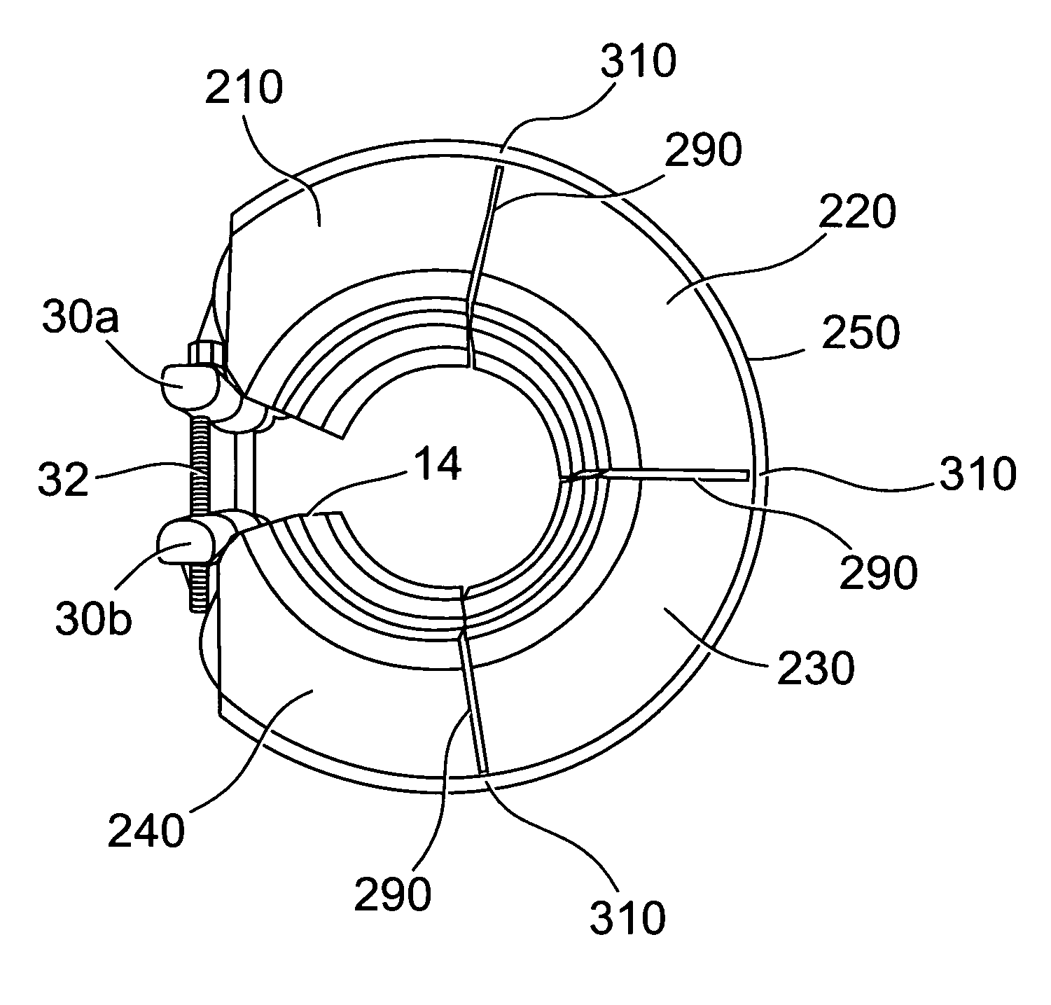
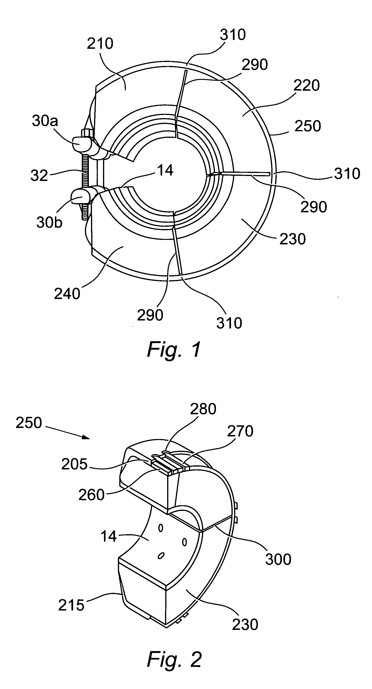
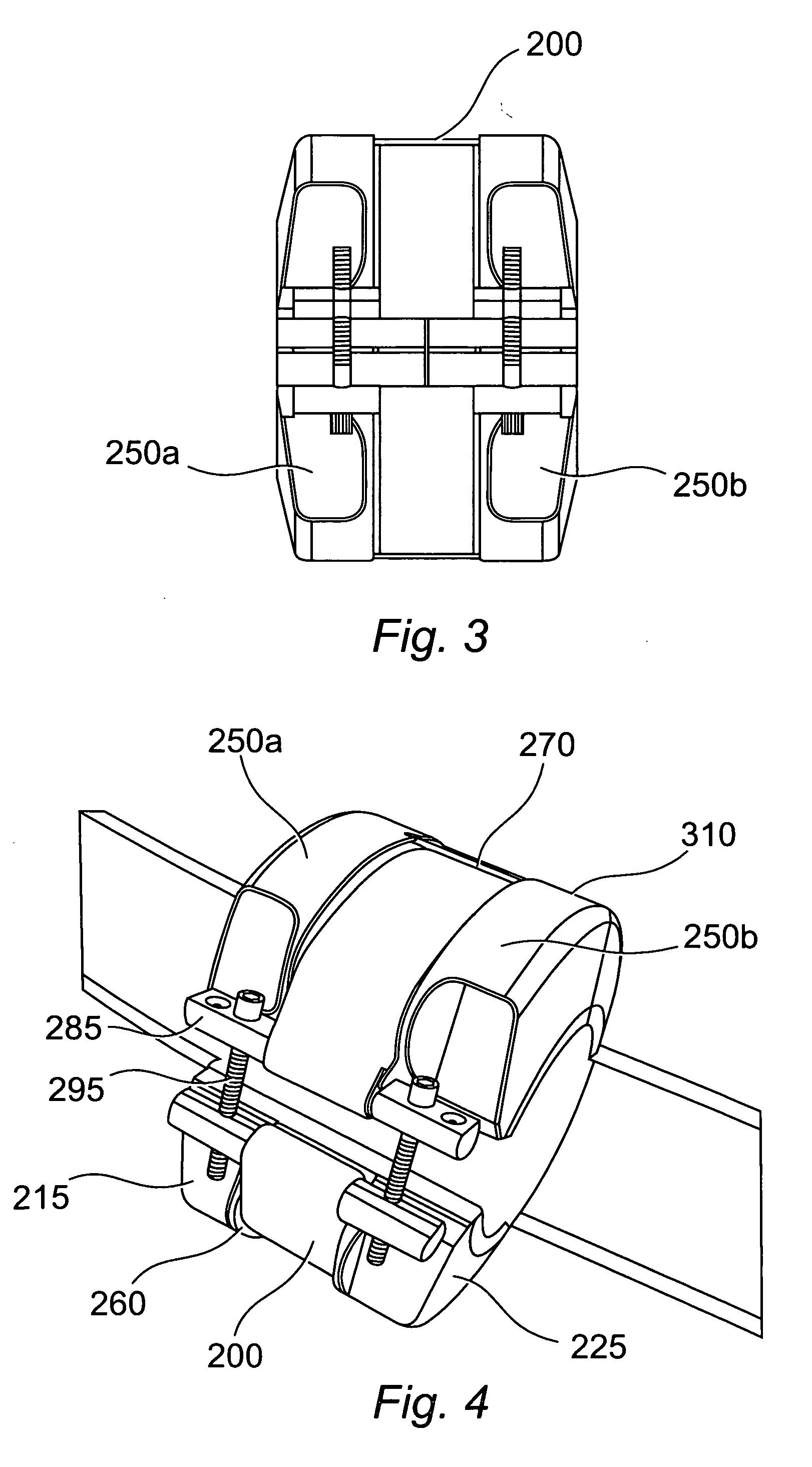
[0035]One embodiment of the clamp is shown in FIGS. 1-4. In this embodiment, the clamp has four segments 210, 220, 230, 240 although other numbers of segments are also envisaged. A plastics jacket 250 is formed over the clamp segments. Preferably the jacket comprises polyurethane which is moulded in place or sprayed onto the segments although other materials such as cast elastomeric materials including polyurea, silicone rubber, polybutadiene, heaet-cure PVC plastisol, or polysulphide may be used.

[0036]The jacket extends over the outer convex face 205 of the segments and also the top and bottom faces 215, 225 of the segments. In the embodiment shown, the jacket extends over substantially the entire top and bottom faces of the segments. However, the amount of coverage may vary depending upon the operational requirements of the clamp and in some embodiments the jacket may only cover the outer convex face of the segments.

[0037]The jacket may be formed in two sections 250a, 250b as show...


PUM


Abstract

A clamp device suitable for attachment to a riser comprisesa clamp body comprising a plurality of segments; an elastomer hinge provided between adjacent segments and extending over an outer surface of the segments; a tensioning band having a connector at each end, and fastening means to draw the connectors together to tension the band.

Description

FIELD OF THE INVENTION[0001]This invention relates to a clamp device for securing buoyancy elements to underwater flowlines.BACKGROUND[0002]In order to extract hydrocarbons from subsea wells, flowlines, often referred to as risers, extend from a wellhead to a surface facility, such as an oil rig. Risers are flexible and bend in response to prevailing underwater conditions. To manufacture flexible risers it is necessary to have an inner tube / tensile layers and an outer plastic sheath for protection from the sea. This sheathing has a low coefficient of friction with the inner tube of the riser and so is relatively delicate.[0003]In order to isolate subsea terminations from the effects of vessel movement under weather and tide effects, buoyancy modules are used to create particular configurations of risers, for example configurations known as ‘Lazy S’, Lazy Wave’, ‘Lazy W’, between a Floating Production Storage and Offtake (FPSO) vessel and the seabed or floating subsea structure.[0004...

Claims


Application Information

Patent Timeline
IPC IPC(8): G09F7/18
CPCE21B17/012F16L1/24F16L3/1211
Inventor STOKES, KEVAN FREDERICK
Owner BALMORAL COMTEC
Learn More