Pressure vessel
a pressure vessel and pressure technology, applied in vessel construction details, transportation and packaging, mechanical devices, etc., can solve the problems of increasing manufacturing costs and increasing manpower hours, and achieve the effect of low cos
- Summary
- Abstract
- Description
- Claims
- Application Information
AI Technical Summary
Benefits of technology
Problems solved by technology
Method used
Image
Examples
embodiment 1
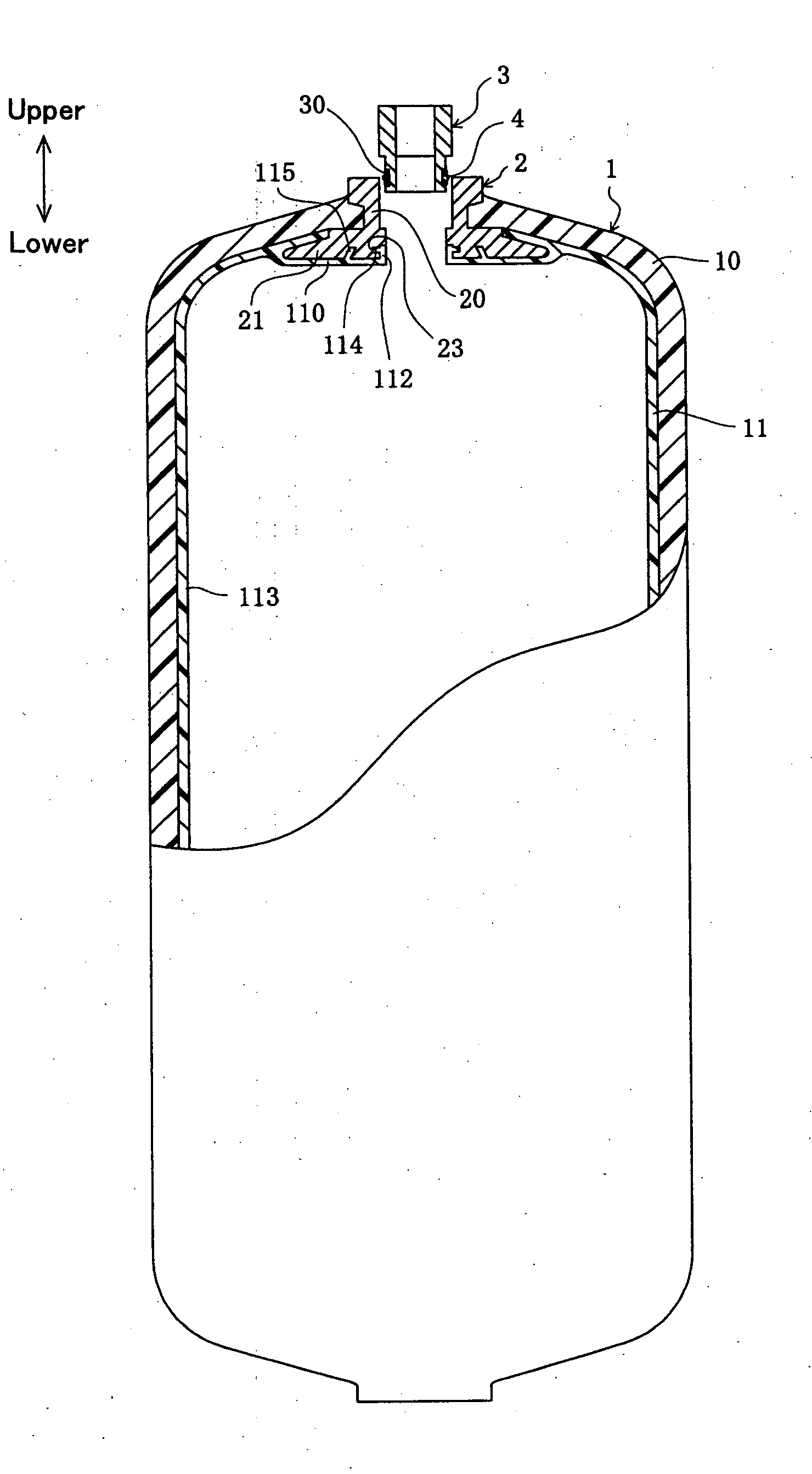
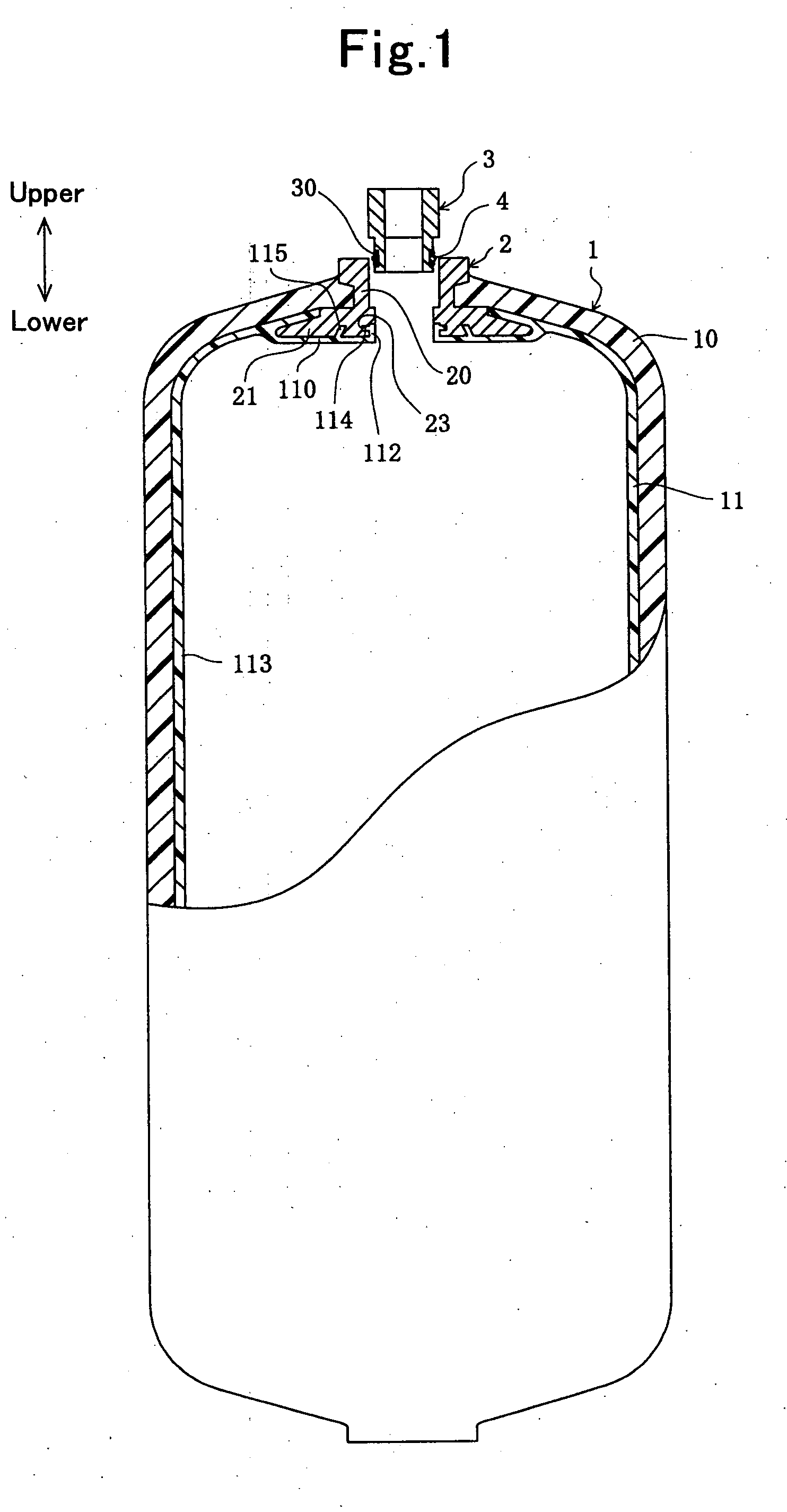
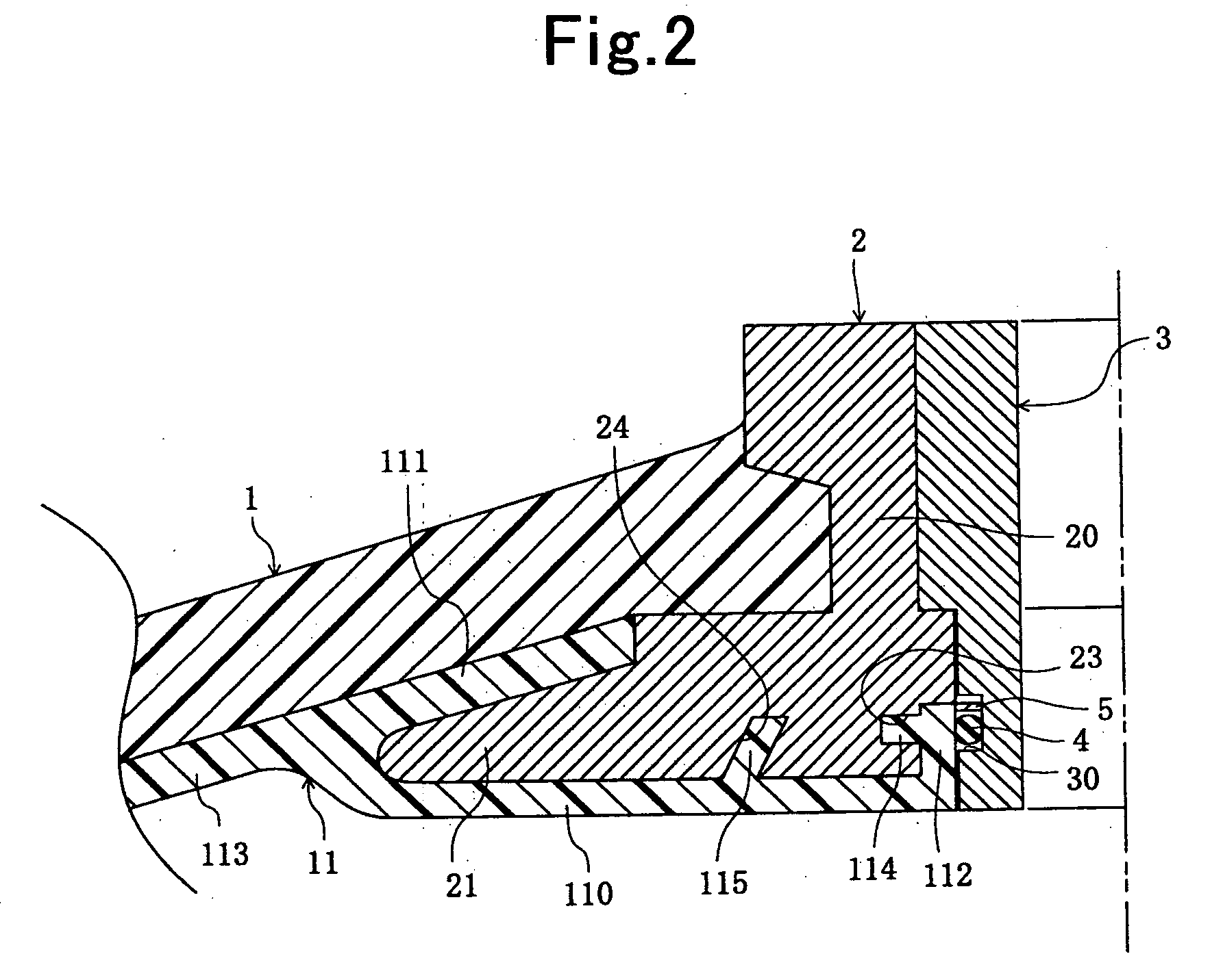
[0027]The pressure vessel of Embodiment 1 is a fuel tank for use in a motor vehicle, and is provided with the above-described arrangement (1). FIG. 1 is a partially cut-away exploded view which schematically shows the pressure vessel of Embodiment 1. FIG. 2 is an enlarged sectional view of a main part of a pressure vessel of Embodiment 1, which schematically shows the state cut in an axial direction thereof. Hereinafter, in Embodiment 1, the terms “upper” and “lower” denote “upper” and “lower” in FIG. 1.
[0028]The pressure vessel of Embodiment 1 is provided with a main body 1, a mouth ring 2 and a valve 3.
[0029]The main body 1 has a cylindrical (tubular) configuration of which two ends positioned in an axial direction thereof (upward and downward in FIG. 1) have reduced diameters. The main body 1 has a reinforcing portion 10 and a liner portion 11. The liner portion 11 is composed of EVOH (ethylene-vinyl alcohol copolymer resin) which is excellent in gas barrier properties. The reinf...
embodiment 2
[0044]The pressure vessel of Embodiment 2 is provided with the above-described arrangements (1) through (3). The pressure vessel of Embodiment 2 is identical to that of Embodiment 1 except that the sealing member is composed of two O rings, and the valve has two grooves for holding the O rings. FIG. 3 is an enlarged sectional view of a main part of the pressure vessel, which schematically shows the state where the pressure vessel is cut in the axial direction thereof. FIG. 4 is an explanation view which schematically shows the pressure vessel of Embodiment 2. Hereinafter, in Embodiment 2, the terms “upper” and “lower” denote “upper” and “lower” in FIG. 3.
[0045]As shown in FIGS. 3 and 4, the pressure vessel of Embodiment 2 has two O rings (first O ring 40, second O ring 41). These O rings 40, 41 correspond to the sealing member in the pressure vessel in accordance with the present invention. Two O ring holding grooves (300, 301) are formed in the valve 3. The O ring holding groove 30...
embodiment 3
[0051]The pressure vessel of Embodiment 3 is provided with the above-described arrangements (1) and (4). The pressure vessel of Embodiment 3 is identical to that of Embodiment 1 except that the sub-sealing member is provided therein. FIG. 5 is an enlarged sectional view of a main part of the pressure vessel, which schematically shows the state where the pressure vessel is cut in the axial direction thereof. Hereinafter, in Embodiment 3, the terms “upper” and “lower” denote “upper” and “lower” in FIG. 5.
[0052]The boss seal part 112 in the pressure vessel of Embodiment 3 covers only the part of the inner peripheral surface of the boss part 20 on the interior side in the axial direction (lower part in FIG. 5). Consequently, the part of the inner peripheral surface of the boss part 20 on the exterior side in the axial direction is exposed to external view.
[0053]An annular first O ring holding groove 30 is formed in the part of the outer peripheral surface of the valve 3 on the interior ...
PUM
| Property | Measurement | Unit |
|---|---|---|
| radial length | aaaaa | aaaaa |
| thickness L1 | aaaaa | aaaaa |
| distance L3 | aaaaa | aaaaa |
Abstract
Description
Claims
Application Information
 - R&D
- Intellectual Property
- Life Sciences
- Materials
- Tech Scout
- Unparalleled Data Quality
- Higher Quality Content
- 60% Fewer Hallucinations
Browse by: Latest US Patents, China's latest patents, Technical Efficacy Thesaurus, Application Domain, Technology Topic, Popular Technical Reports.
© 2025 PatSnap. All rights reserved.Legal|Privacy policy|Modern Slavery Act Transparency Statement|Sitemap|About US| Contact US: help@patsnap.com


