
Fast impedance protection technique immune to dynamic errors of capacitive voltage transformers

a capacitive voltage transformer and impedance protection technology, applied in the direction of electrical equipment, arrangements resposes to fault current, impedence measurement, etc., can solve the problem of changing system voltage and/or current, and affecting the stability of the entire power system. , to achieve the effect of a shorter window and a faster operating tim

Active Publication Date: 2008-10-02
GENERAL ELECTRIC CO
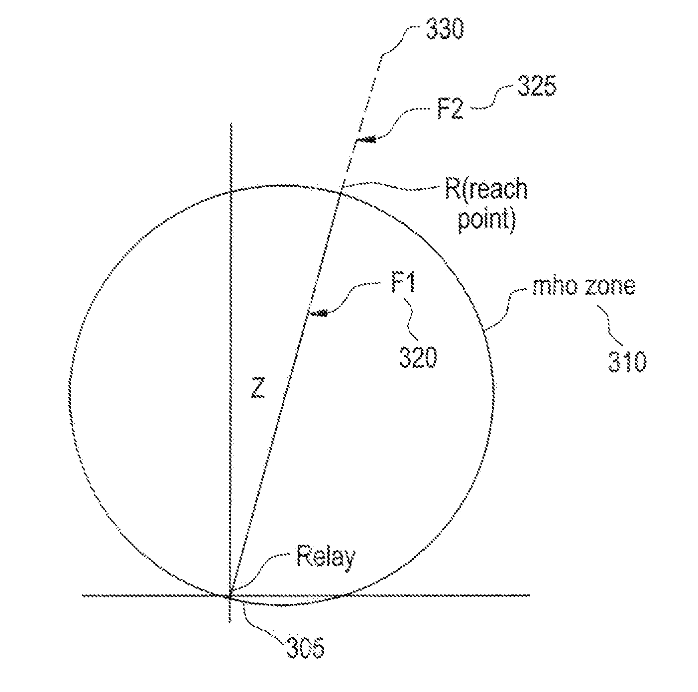
View PDF18 Cites 16 Cited by
  • Summary
  • Abstract
  • Description
  • Claims
  • Application Information

AI Technical Summary

Problems solved by technology

A failure often takes the form of an insulation breakdown (fault) that result in a change in the system voltage and / or current.
Further, the longer a fault persists in a power system, the greater the likelihood that the stability of the entire power system will be compromised.
The approach is problematic since the time that is required to detect a fault is a function of the length of the Fourier window, thus a shorter window generally produces a faster operating time.
However, as the length, of a window is shortened it becomes more difficult to discriminate between the fundamental frequency component and other components.
Similarly, Capacitive Voltage Transformers (CVTs), are resistance variations, shunt capacitance, and traveling waves effects also generate transients that negatively impact the phasor estimation process.
CVTs create a particular challenge for fast impedance protection functions, particularily under so called high Source to Impedance Ratios (SIRs).
This makes them very difficult to filter out particularly within the short time period in which protective relays are expected to operate.
While this approach can produce faster operation times for faults located close to the relay, it does not improve the performance throughout the zone protected by the relay.

Method used


Image

  • Fast impedance protection technique immune to dynamic errors of capacitive voltage transformers
  • Fast impedance protection technique immune to dynamic errors of capacitive voltage transformers
  • Fast impedance protection technique immune to dynamic errors of capacitive voltage transformers

Examples


Embodiment Construction

[0027]One or more exemplary embodiments of the invention are described below in detail. The disclosed embodiments are intended to be illustrative only since numerous modifications and variations therein will be apparent to those of ordinary skill in the art.

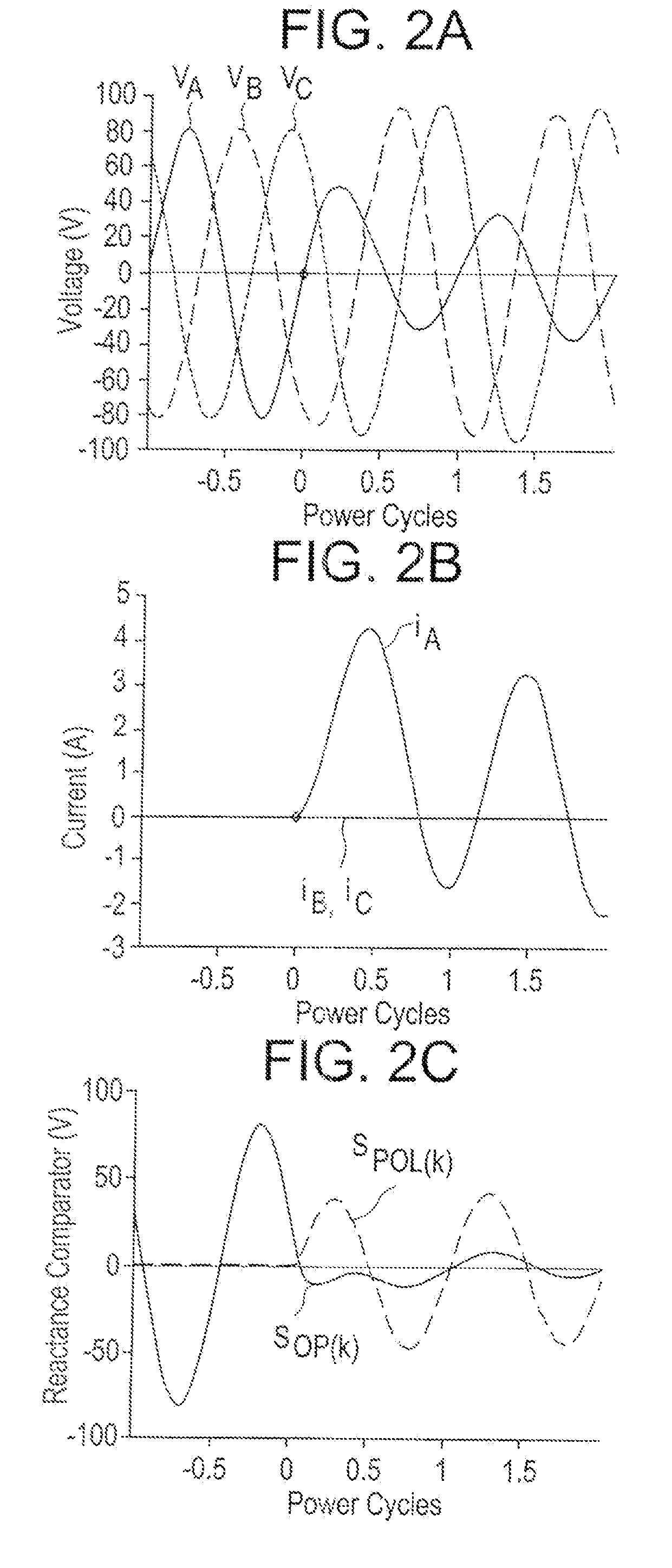
[0028]Aspects of the present invention generally relate to an impedance algorithm that can identity faults within its zone by processing samples of the waveforms in the time domain—without the need of a DFT. The time required for detection is less than one power cycle for faults throughout much of the zone of protection. Aspects of the invention form the traditional impedance characteristics of a distance relay such as mho, reactance, blinders, phase selection and other as per the art of impedance protection but in the time domain rather than the frequency domain.

[0029]The traditional frequency domain approach to impedance protection extracts phasors of currents and voltages, and applies the impedance characteristics to the phaso...


PUM


Abstract

The present invention relates to methods for providing impedance protection differentiating between in-zone and out-of-zone faults based on instantaneous, digitally derived operating and polarizing, distance comparator signals. The method uses a pair of fast orthogonal filters to derive D and Q components of the input voltages and currents. Two sets of operating and polarizing signals are derived for better speed of response under varying fault moment with respect to the peaks and zero crossings of power signals. Three stages of comparison between the operating and polarizing impedance terms are used. These comparator stages use half a cycle averaging windows, and three-quarters-of-a-cycle windows. The first stage of comparison is based on energy comparator responding to both magnitude and phase information in the signals. Stages 2 and 3 are of phase comparison type, responding mostly at the phase information and neglecting the magnitude information for better immunity to noise and signal distortions.

Description

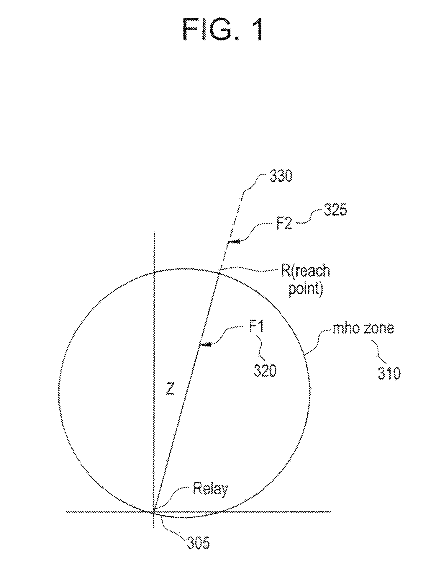
BACKGROUND OF THE INVENTION[0001]1. Field of the Invention[0002]This invention relates to the fast and accurate detection of faults on transmission lines in the presence of noise, and particularly to transients caused by Capacitive Voltage Transformers.[0003]2. Description of Background[0004]Protective relays are devices that are designed, to identify and isolate failures in a power system. A failure often takes the form of an insulation breakdown (fault) that result in a change in the system voltage and / or current. Protective relays are applied in the power system in such a way that each relay is configured to detect failures within a specific portion of the power system commonly referred to as a zone.[0005]Impedance relays respond to current and voltage as a function of the electrical impedance between the relay location and the location of the fault. The configuration parameter that defines the zone of a distance relay is commonly referred to as the reach. A protective relay shou...

Claims


Application Information

Patent Timeline
Patent Type & Authority Applications(United States)
IPC IPC(8): H02H3/16
CPCH02H3/402G01R27/16
Inventor KASZTENNY, BOGDAN Z.FINNEY, DALE S.RADUCANU, IULIAN
Owner GENERAL ELECTRIC CO
Learn More