
Head mounted display device

a display device and display device technology, applied in the field can solve the problems of ametropic eye correction, ametropic eye correction is associated with considerable complexity, wear of hmd device with spectacles is often viewed as unpleasant, etc., and achieves the effects of simple assembly, high precision of guidance, and easy introduction

Active Publication Date: 2008-10-02
MICROOLED BHT
View PDF7 Cites 55 Cited by
  • Summary
  • Abstract
  • Description
  • Claims
  • Application Information

AI Technical Summary

Benefits of technology

[0012]In view of the above, it is an object of the invention to provide an HMD device which is suitable for emmetropic users as well for different users whose eyes exhibit ametropia. It is a further object of the invention to provide such an HMD device which is of simple construction and is convenient to operate.

Problems solved by technology

A disadvantage is that a user whose eye is ametropic must make an ametropic correction.
The wearing of the HMD device together with the spectacles is, however, often viewed as being unpleasant.
In each case, an ametropic correction is associated with considerable complexity insofar as this correction is even provided for.
It is a disadvantage that the knurled screws project at both sides of the head of the wearer.
The arrangement is technically complex.
The arrangement is difficult to operate and is technically complex and has a comparatively large length expansion.

Method used


Image

  • Head mounted display device
  • Head mounted display device
  • Head mounted display device

Examples


Embodiment Construction

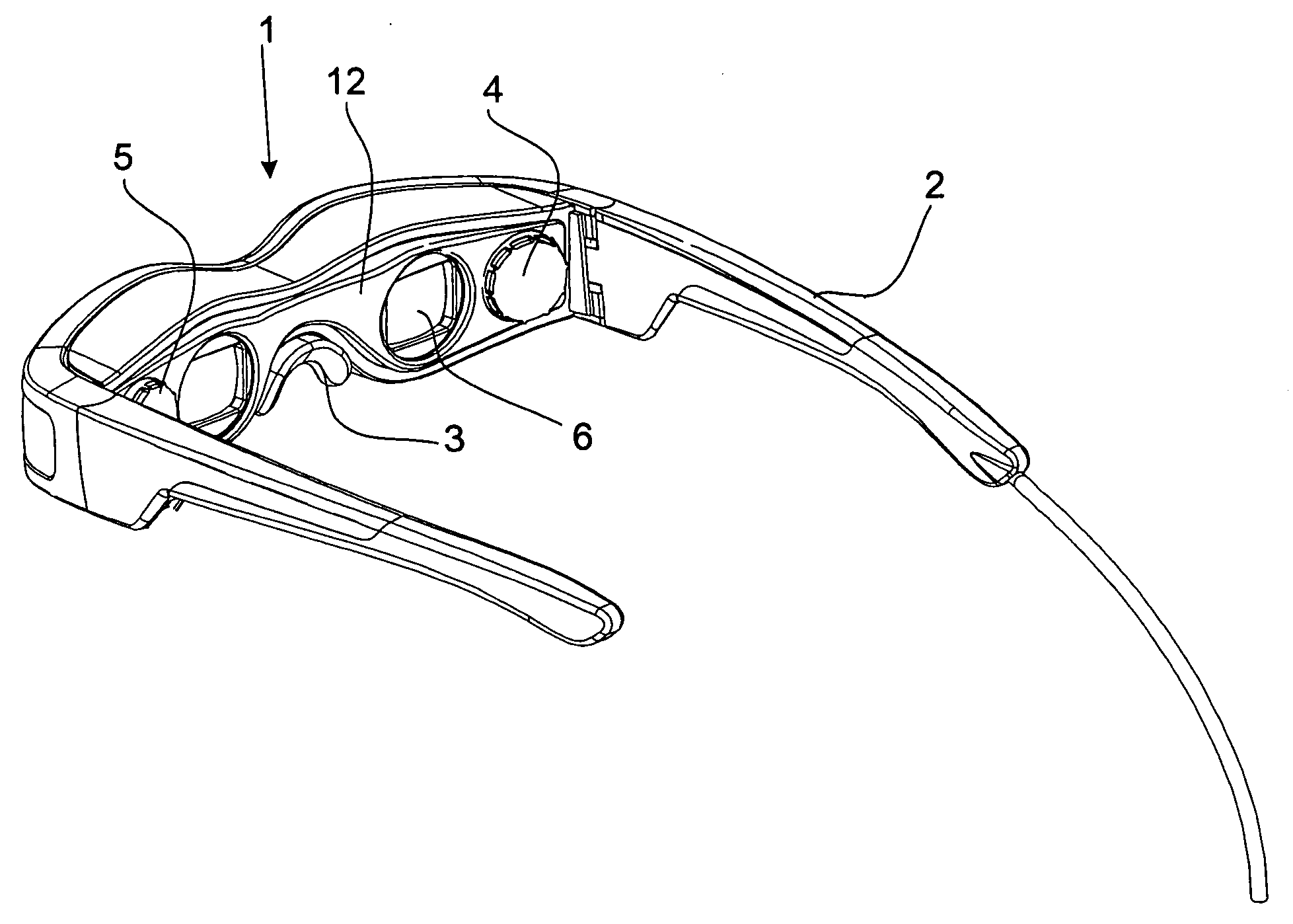
[0032]FIG. 1 is a perspective view of an HMD device which is configured in the manner of spectacles. A support frame 12 supports respective pivotable temples 2 on the left and right sides and a nose bridge 3 is provided at the center of the frame 12. The frame 12 has respective image windows 6 for the right and left eyes of a viewer. A right adjusting wheel 4 is mounted between the right image window 6 and the right temple 2 and a left adjusting wheel 5 is mounted between the left image window 6 and the left temple 2. The ametropia of the right eye and of the left eye are individually compensated by actuating the right and / or left adjusting wheels (4, 5).

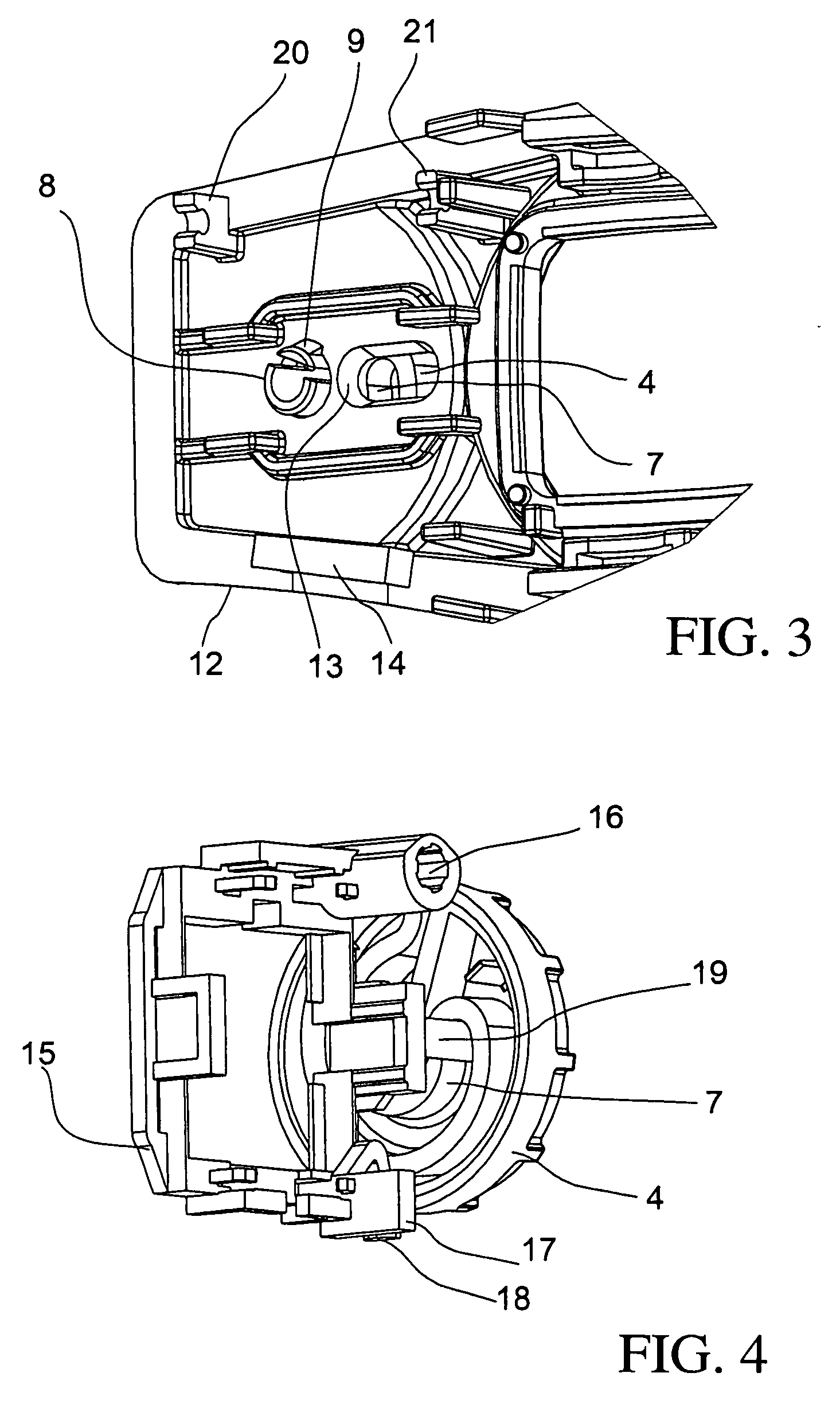
[0033]FIG. 2 shows the configuration of the right and left adjusting wheels (4, 5) which are structurally the same. The adjusting wheel has a slotted insert shaft 8. A snap hook 9 projecting outwardly is mounted on a portion of the insert shaft 8. In addition, a slot cam 7 is machined into the adjusting wheel (4, 5) approximately 34...


PUM


Abstract

An HMD device has an imaging optic for the right eye and an imaging optic for the left eye. Each imaging optic so images an image, which is generated in the object plane, that the image can be observed by a user in an image plane and each of the imaging optics includes an optical element (23) and a deflecting element (25) mounted downstream of the optical element (23). An image transducer (24) and the optical element (23), which follows the image transducer (24), are held by a linearly guided receptacle frame (15) moveable via a drive unit. A linear movement in the direction of an optical axis takes place. Adjusting wheels (4, 5) are mounted on respective sides of the image window for the right and left eyes. Each of the adjusting wheels (4, 5) is coupled mechanically to a corresponding cam curve. Each cam curve translates a rotational movement of the adjusting wheel (4, 5) into an output end linear movement of the receptacle frame (15).

Description

CROSS REFERENCE TO RELATED APPLICATION[0001]This application claims priority of German patent application no. 10 2007 016 138.9, filed Mar. 29, 2007, the entire content of which is incorporated herein by reference.FIELD OF THE INVENTION[0002]The invention relates to a head mounted display device (HMD device) having an imaging optic for the right eye and an imaging optic for the left eye. Each imaging optic so images an image, which is generated in the object plane, that a user can observe the image in an image plane. Each of the imaging optics includes an optical element and a deflecting element mounted downstream of the optical element.BACKGROUND OF THE INVENTION[0003]An imaging optic of this kind is disclosed, for example, in U.S. Pat. No. 6,903,875. The imaging optic for the display unit is computed for an emmetropic eye. A disadvantage is that a user whose eye is ametropic must make an ametropic correction.[0004]The solution described in U.S. Pat. No. 6,977,776 uses an HMD devic...

Claims


Application Information

Patent Timeline
Patent Type & Authority Applications(United States)
IPC IPC(8): G02B7/06
CPCG02B27/0172G02B27/0176G02B2027/011
Inventor BECK, KLAUSRUDOLPH, GUNTER
Owner MICROOLED BHT
Learn More