
Fingerprint identification system

a fingerprint identification and fingerprint technology, applied in the field of fingerprint identification system, can solve the problems of large space in the fingerprint identification system of the prior art, a number of flaws in the prior art, and a large amount of space not fully utilized, so as to reduce production output and acceptance rate, and prolong the production cycle

Inactive Publication Date: 2008-10-02
CHUAN LIANG IND
View PDF3 Cites 25 Cited by
  • Summary
  • Abstract
  • Description
  • Claims
  • Application Information

AI Technical Summary

Benefits of technology

[0009]The primary purpose of the present invention is to provide a fingerprint ID system to solve problems found with the prior art including failure in effective reduction in size due to optical limitations, longer production cycle, and lower production output and acceptance rate due to pursuit of device precise alignment at the cost of shifting to manual assembly and test.
[0011]In the configuration as described above, the present invention further utilizes its free area pervious to light to integrate the device pervious to light and a flat reflection plane group into a device, so to reduce the size of the fingerprint ID system and significantly upgrade automated precision assembly and ease of alignment among devices for effectively lowering production cost and cycle.
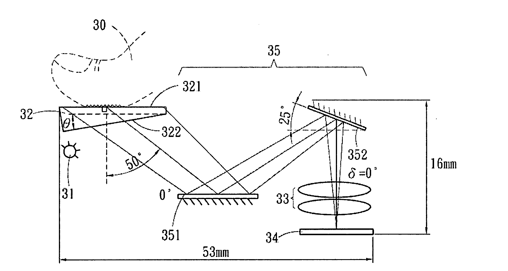
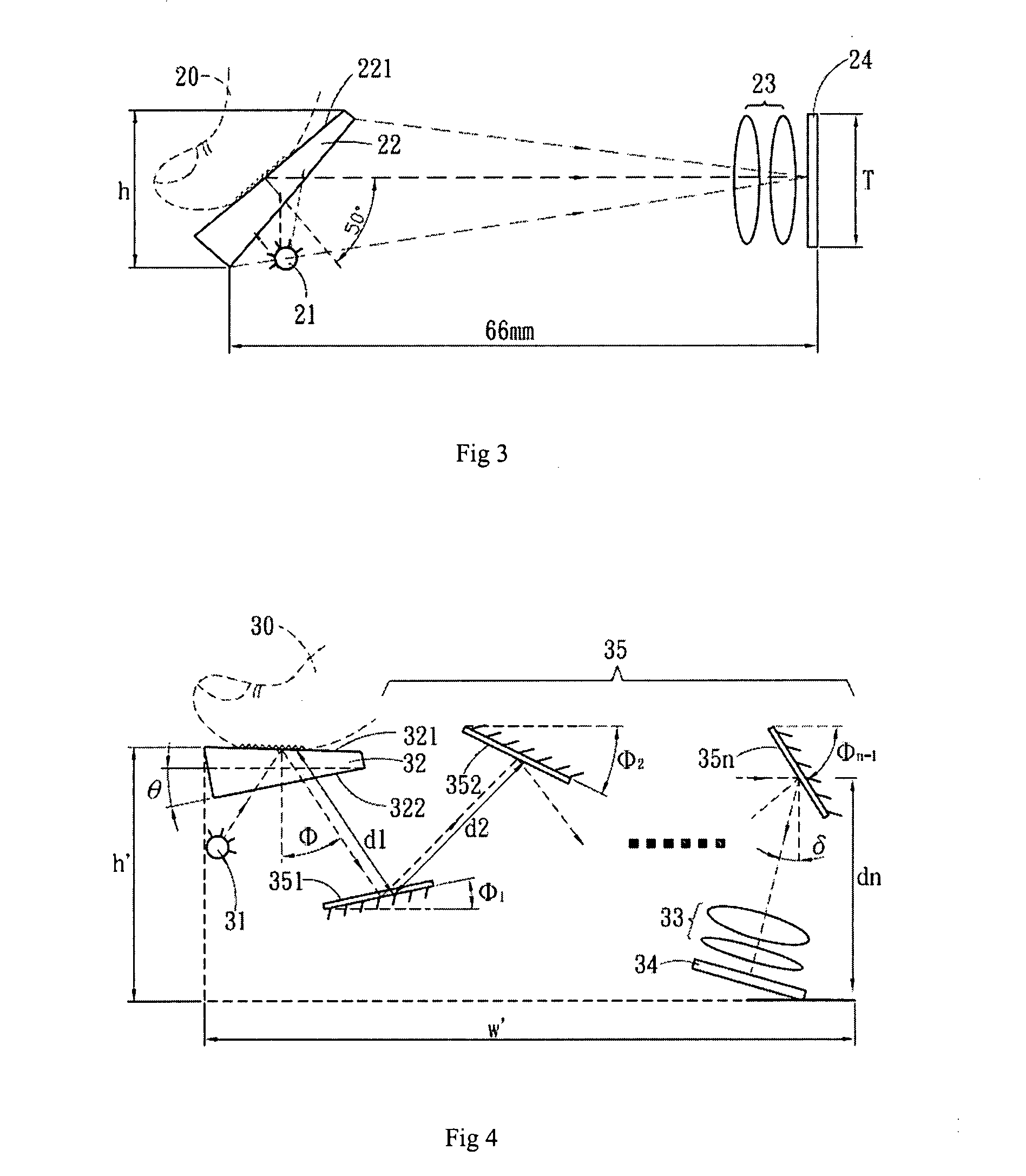
[0016]Another preferred embodiment yet of the present invention is characterized in having the device pervious to light and the reflection device group into a free-form prism. Wherein, the fingerprint ID system includes a light source, a free-form prism made either of glass or plastic material pervious to light or combination of both. The free-form prism is provided with a fingerprint side to contact a finger and the beam emitted from the light source directly irradiates on the fingerprint side before reflecting the image of the fingerprint. The angle between the fingerprint side and the beam from the light source is controlled to retrieve the fingerprint of total internal reflection. On one side of the free-form prism is disposed with an total internal reflection plane group to such that the optical path of the reflected beam is located inside the free-form prism; a lens unit comprised of one or a plurality of spherical lens, aspherical lens, and diffraction device so that the final beam reflected by the reflection device group is focused to form an image; and an image sensor to receive the image formed. Wherein, the total internal reflection plane group is comprised of multiple flat reflective planes; and the angle and position of each total internal reflection plane must meet the imaging principles of a flat mirror with the last internal reflection plane to reflect stream of light into the convex lens to finally form an image on the image sensor device. A reflection device related to a film plated flat reflection plane is further disposed to each total internal reflection plane in the total internal reflection plane group to enhance the total reflection results.

Problems solved by technology

The optical path involved reveals a number of flaws about the prior art.
Size, among others, is a problem.
There is a lot of space in the fingerprint ID system of the prior art not fully utilized due to that the light travels in straight line fashion.
For being restricted by optical characteristics including focusing, it is difficult for the fingerprint ID system of the prior art to have breakthrough in reducing its installation size.
Another problem found with the prior art is also attributable to optical characteristics.
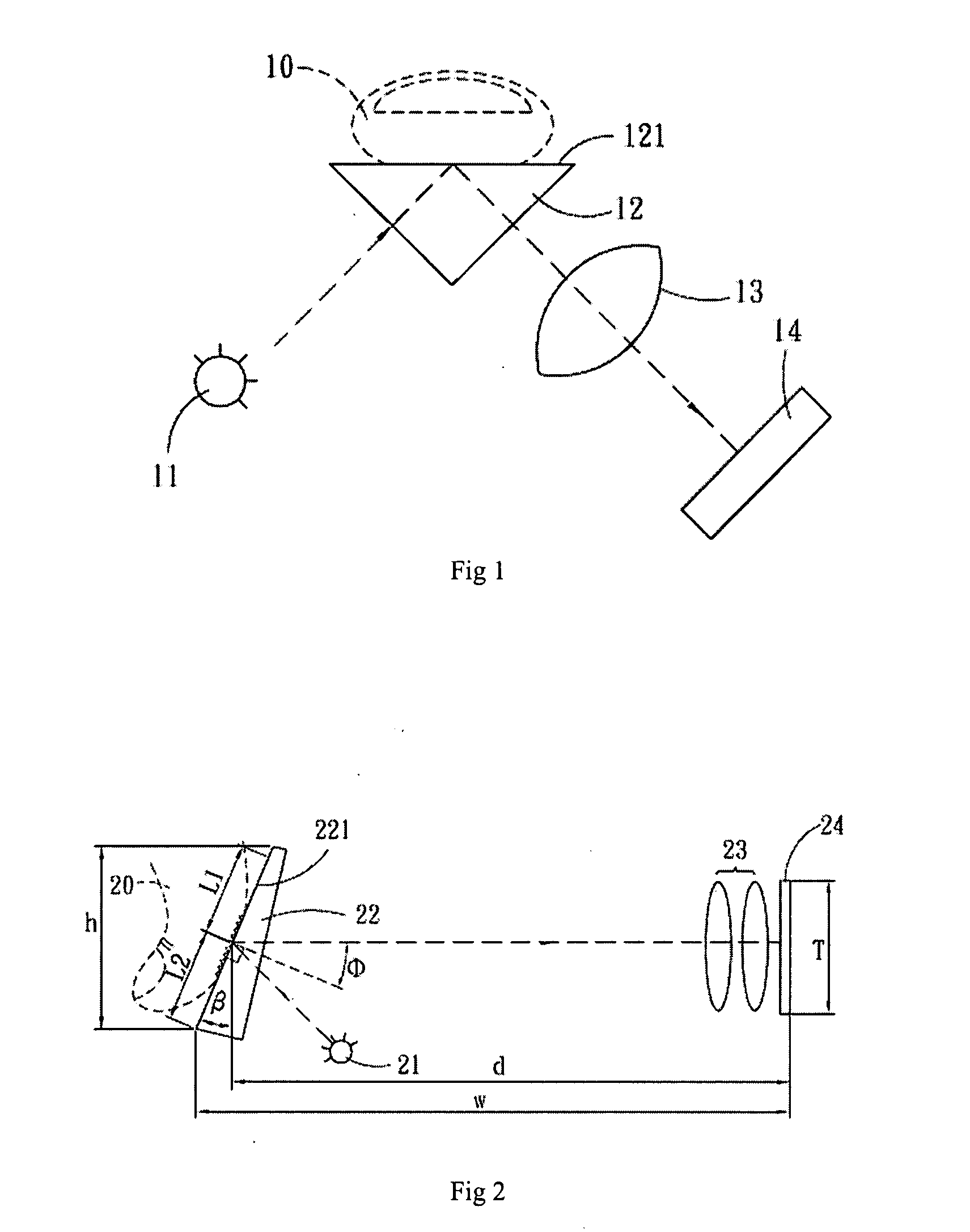
Since the beam must be focused on the image sensor 24 through the convex lens, any error of relative positions among the device 22 pervious to light, the convex lens, and the image sensor 24 would result in poor focusing, thus leading to poor image signals.
Therefore, those relative positions among the device 22 pervious to light, the convex lens, and the image sensor 24 must be precisely accurate, a demand that is very difficult to meet due to that the assembly of those devices is done in an automated manufacturing process.
Furthermore, product acceptance rate may be a problem since the manual assembly is not necessarily reliable.

Method used


Image

  • Fingerprint identification system
  • Fingerprint identification system
  • Fingerprint identification system

Examples


Embodiment Construction

[0027]Referring to FIG. 4 for a schematic view of a first preferred embodiment of the present invention, a fingerprint ID system includes a light source 31 to directly irradiate beams on a wedge shaped device 32 pervious to light, and the device 32 is made either of glass or plastic material, or a combination of both. A fingerprint side 321 contacts a finger 30 is disposed on the device 32 to retrieve an total internal reflection fingerprint image by controlling an angle θ defined by the fingerprint side 321 and a beam output side 322 of the device 32. The angle θ ranges between 0°˜45° and an included angle defined by the light output side 322 and a bottom of the system is not necessarily at a right angle thus to reduce the volume of conventional device pervious to light in the fingerprint ID system. A reflection device group 35 is disposed behind the device 32 pervious to light for the purpose to allow transit of beams fully utilize the space. The final beam arrives at a lens unit ...


PUM


Abstract

A fingerprint ID system providing function of compressed volume of the fingerprint ID system is comprised of adding a reflection device group between fingerprint plane of the device pervious to light and imaging plane of an image sensor; and the device pervious to light and a flat reflection plane group is integrated into one device for reducing the size of the fingerprint ID system and significantly upgrading automated precision assembly and easier alignment of devices to effectively reduce production cost and shorten production cycle.

Description

BACKGROUND OF THE INVENTION[0001](a) Field of the Invention[0002]The present invention is related to a fingerprint ID system, and more particularly, to one that achieves compressing system volume effects by using a new method to transit optical path.[0003](b) Description of the Prior Art[0004]Existing fingerprint ID systems generally apply and integral prism, convex lens and image sensor device as the primary devices to catch image of fingerprint. FIG. 1 of the accompanying drawings is a schematic view of a fingerprint ID system of the prior art. Wherein, a visible beam emitted from a light source 11 enters into one side of a prism 12 and advances in the prism 12 heading for a fingerprint side 121 that contacts a finger 10 while reflecting an image formed by having the finger 10 to contact the fingerprint side 121 to another side of the prism 12; in turn the image is focused through a convex lens 13 on an image sensor 14 before executing proper signal process to complete identificat...

Claims


Application Information

Patent Timeline
Patent Type & Authority Applications(United States)
IPC IPC(8): G06K9/74
CPCG06K9/00046G06V40/1324
Inventor WANG, MENG-HUAWANG, TZU-TE
Owner CHUAN LIANG IND
Learn More