
Noise isolating underlayment

a technology of noise isolating underlayment and underlayment, which is applied in the direction of resiliently-mounted floors, walls, transportation and packaging, etc., can solve the problems of poor sound or acoustic properties, impact noise isolation, and poor acoustic properties of materials with regard to structure-borne sound transmission, so as to improve the impact noise isolating properties of the underlayment and achieve exceptional performance. , the effect of maintaining strength characteristics

Active Publication Date: 2008-10-02
PACIFIC COAST BUILDING PRODS
View PDF99 Cites 36 Cited by
  • Summary
  • Abstract
  • Description
  • Claims
  • Application Information

AI Technical Summary

Benefits of technology

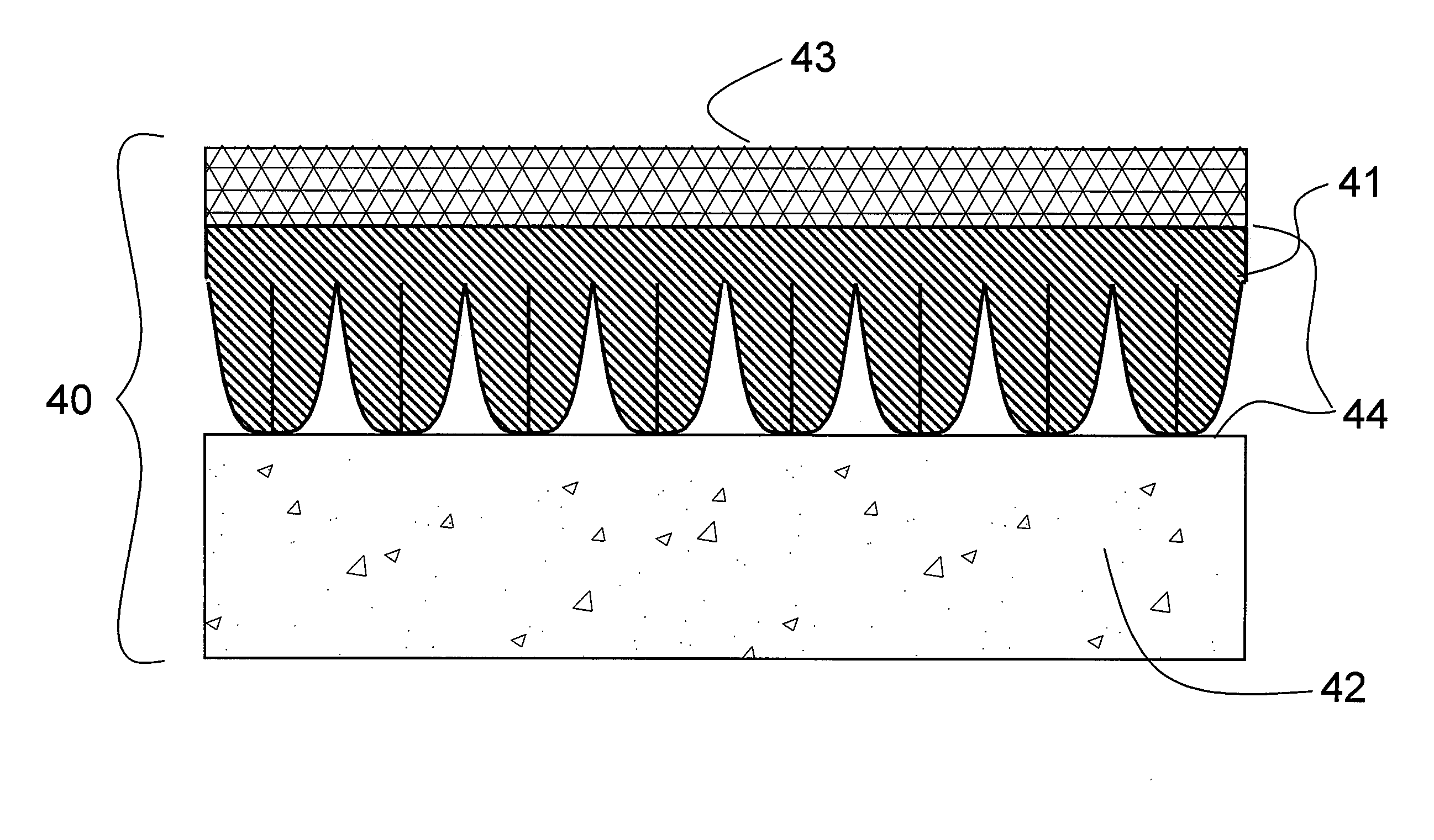
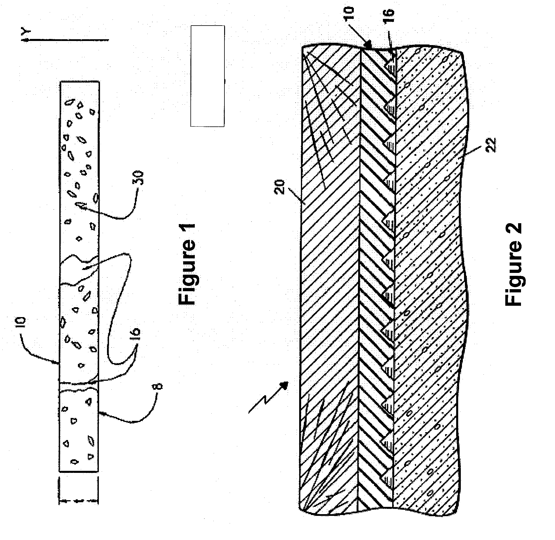
[0010]The present invention provides an impact noise isolating underlayment having exceptional performance with an acceptable thickness for use with rigid decorative flooring including tile and laminated wood flooring and the like. As a feature of the invention, the isolation enhancing profile is oriented across the bottom surface of the underlayment so as not to allow possible alignment of one or more characteristics of the profile with the edges of any rigid decorative tile or plank. As an additional feature of the invention, improved impact noise isolating properties of the underlayment are provided compared to the prior art while maintaining the strength characteristics required to be used without an additional structural layer in such a flooring system. More specifically, in accordance with this invention, a noise isolating substrate is provided as an underlayment in a flooring structure including a subfloor. The substrate comprises a solid resilient material with a bottom surface sized to cover a given surface area, a top surface, and side edges. The bottom surface is provided with regularly arrayed knobs or protuberances whereby only a portion of the bottom surface is in contact with the subfloor. The surface ratio of the portion of bottom surface in contact with the subfloor to the given surface area covered by the bottom surface ranges from 15 to 50%, preferably from 15 to 35% and more preferably from 15 to 25%. It has been found that by reducing the portion of the bottom surface in contact with the subfloor the effective dynamic stiffness of the underlayment is lowered and thus the structure-borne energy which is transferred by the flooring structure when an object strikes the top floor surface is reduced. The resulting noise isolation of the overall flooring system structure is greatly improved.

Problems solved by technology

However, despite their numerous desirable qualities, these materials typically exhibit poor acoustic properties with regard to structure-borne sound transmission.
Poor sound or acoustic properties are extremely undesirable in all structures, but in particular in high-rise office buildings, hotels, apartments, and the like.
Impact noise isolation is a current building design issue as evidenced by the fact that almost all contemporary model building codes establish a minimum impact noise isolation between occupied living units.
Notably, most descriptions of these prior art structures incorrectly credit the cellular composition or resulting internal voids as an acoustic energy dissipating mechanism rather than correctly describing these features as reducing the underlayment's effective dynamic stiffness and thereby improving the impact isolation of the underlayment.
If the underlayment material is soft or the void fraction high (resulting in an underlayment that is soft) then the installed sheet is unable to support tile or any other rigid topping material without allowing the tile or rigid topping material to crack.
This additional step adds to the installed cost and overall height of the system.
Although such mats lack a cellular structure or predictable void fraction, their material characteristics and limitations are the same.
Other prior art underlayment layers use a homogeneous material that is profiled or coped with engineered voids to reduce the effective dynamic stiffness of the underlayment.
A potential problem with the underlayment described by U.S. Pat. No. 6,213,252 is that the parallel grooves may inadvertently align with the parallel edges of the overlying ceramic tile or wood flooring planks allowing the system to form a fissure at the grout, across a tile, or between wood panels.
Though the hard material exhibits poor noise isolation, it allows the rigid decorative flooring material to be directly installed over the underlayment.
Although homogeneous mats exist, they must be unacceptably thin and / or rigid to allow direct installation of an overlaying rigid decorative layer.
However, improved impact noise isolation via lower dynamic stiffness and greater mat thickness are structurally insufficient to allow a decorative topping layer such as tile to be directly applied to the underlayment.
Without the additional support of a rigid top surface layer, the overlaying tiles or laminated flooring would crack and deform as pressure is applied.
The introduction of the support layer further adds to the height requirements, resulting in greater expense.

Method used


Image

  • Noise isolating underlayment
  • Noise isolating underlayment
  • Noise isolating underlayment

Examples


Embodiment Construction

[0025]The following written description is illustrative only and not limiting. The performance of an isolation system is best characterized by its isolation efficiency, I, which is given by I=1−T. The transmissibility, T, indicates the fraction of the energy of the disturbing motion, in this case impact noise, that is transmitted across the assembly. Therefore, the isolation efficiency indicates the fraction by which the transmitted disturbance energy is less than the energy of the excitation noise. Isolation efficiency can be expressed as a percent. If the transmissibility is 0.0075, the isolation efficiency is 0.9925 or 99.25% efficient. 99.25% of the energy does not get through the system.

[0026]Transmissibility may be calculated by the following equation:

T=1+(2·ζ·r)2(1-r2)2+(2·ζ·r)2Eq.1

where r=fd / fn is the ratio of the frequency of the disturbance to that of the natural frequency of the mass-spring system and ζ is the damping ratio. FIG. 3 represents the flooring system 20 schema...


PUM

PropertyMeasurementUnit
Fractionaaaaaaaaaa
Fractionaaaaaaaaaa
Weightaaaaaaaaaa

Abstract

A noise-reducing substrate for use in a flooring system, the flooring system having a subfloor and a decorative upper layer. The substrate comprises a series of edge butted panels, each of which has a bottom surface, a top surface and side surfaces. Each panel's top surface and oppositely facing bottom surface are parallel to each other and are spaced apart by the thickness of the substrate. A profile in the bottom surface of the substrate changes the substrate's effective stiffness and improves the noise isolation of the substrate compared to the stiffness and noise isolation of the panel without the profile. Additionally, the profile reduces the weight of the panel, thereby reducing manufacturing and installation costs. When the substrate is positioned between the subfloor and the decorative top layer, the material hardness and the flat profile of the upper surface provide a platform with the strength and texture required to allow for installation of the decorative floor layer without the need for an additional rigid backing material. Such a system greatly improves the impact noise reduction on a variety of floor / ceiling systems while keeping the installation cost low and the adding very little to the total system thickness.

Description

FIELD OF THE INVENTION[0001]This invention relates to noise isolating material for use in flooring and in particular to a sound insulating material possessing the strength characteristics required to properly support the decorative top layer of the flooring and the dynamic stiffness required to best isolate impact noise.BACKGROUND OF THE INVENTION[0002]The demand for rigid decorative flooring materials such as ceramic and masonry tiles and wood laminate flooring in the construction industry has grown over recent years. These materials are, among other qualities, durable, easy to maintain, and attractive. However, despite their numerous desirable qualities, these materials typically exhibit poor acoustic properties with regard to structure-borne sound transmission. Specifically, the noises generated by footfalls or other periodic impacts are readily transmitted to other parts of the building—especially the rooms below. Poor sound or acoustic properties are extremely undesirable in al...

Claims


Application Information

Patent Timeline
IPC IPC(8): E04C2/26
CPCE04C2/20E04C2/326E04F15/181Y10T428/24479E04F2290/043Y10T428/24678E04F15/20E04F15/185E04F15/203
Inventor TINIANOV, BRANDON
Owner PACIFIC COAST BUILDING PRODS
Learn More