
Electric vacuum cleaner

a vacuum cleaner and electric technology, applied in the field of electric vacuum cleaners, can solve the problems of increasing maintenance difficulty, reducing suction power, etc., and achieve the effects of reducing suction amount, clogging of filter, and increasing air passage resistance of the first air passage sid

Inactive Publication Date: 2008-10-02
KK TOSHIBA +2
View PDF2 Cites 31 Cited by
  • Summary
  • Abstract
  • Description
  • Claims
  • Application Information

AI Technical Summary

Benefits of technology

[0008]In the suctioning state, even if the amount of dust trapped in the dust collecting unit of the main air passage is increased, air suctioned from the suction port is branched into the first air passage, and reduction in a suction amount is suppressed. When the suctioning state is switched to the dust moving state, the dust trapped in the filter is moved to the dust collecting unit, increase in the air passage resistance of the first air passage side caused by clogging of the filter is suppressed, and thus reduction in suction power over time can be suppressed, and the dust collecting unit is exposed, with the lid body opened, by providing at least a part of each of the first and second air passages in the lid body, whereby maintenance performance of the dust collecting unit is improved.

Problems solved by technology

Accordingly, the above electric vacuum cleaner has a problem that, in the case where the filter is clogged over time, suction power is gradually reduced in accordance with the degree of the clogging.
Additionally, even if a mechanism is additionally provided that prevents the filter from being clogged, there arises a problem that maintenance becomes difficult.

Method used


Image

  • Electric vacuum cleaner
  • Electric vacuum cleaner
  • Electric vacuum cleaner

Examples


first embodiment

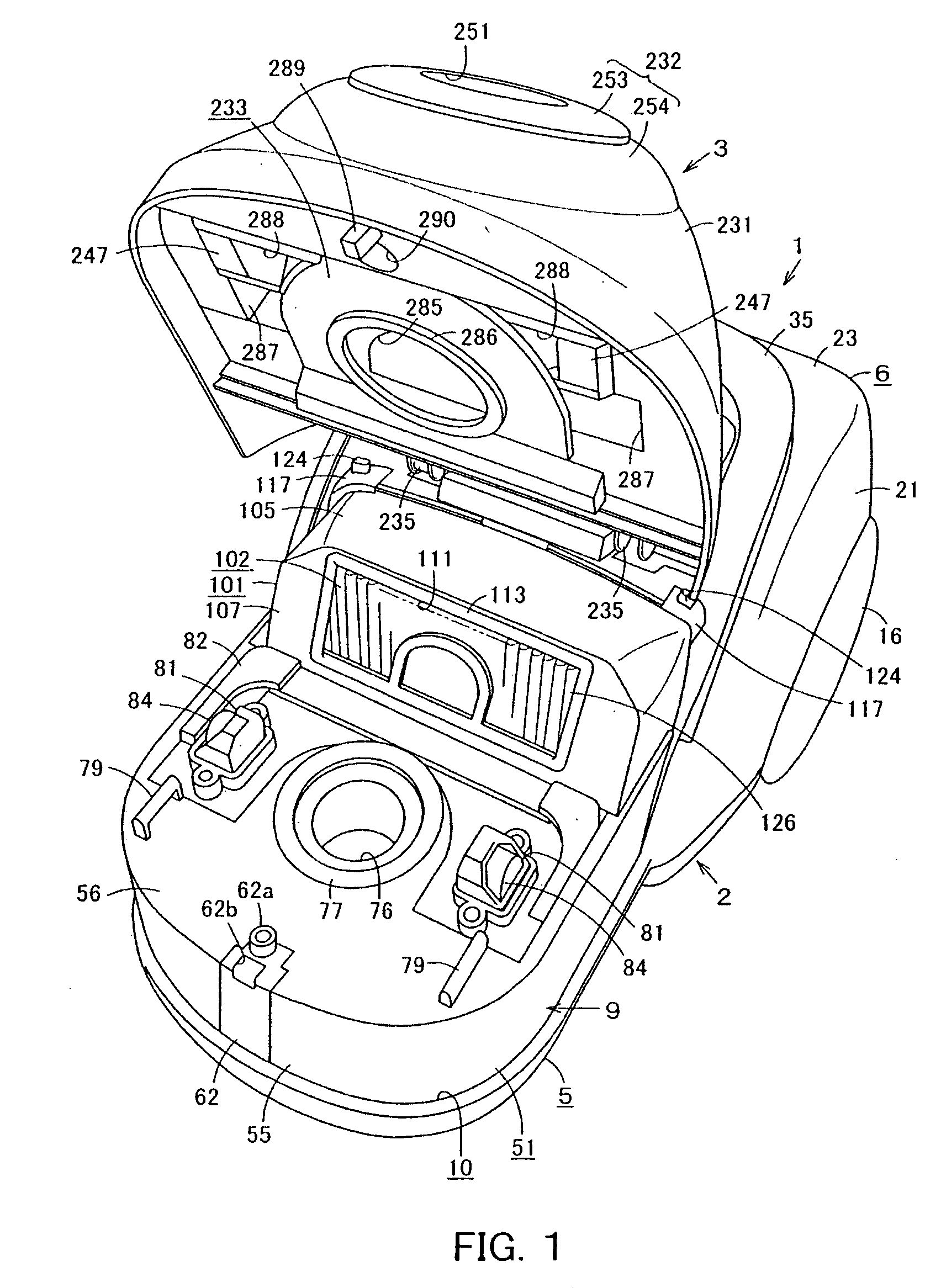
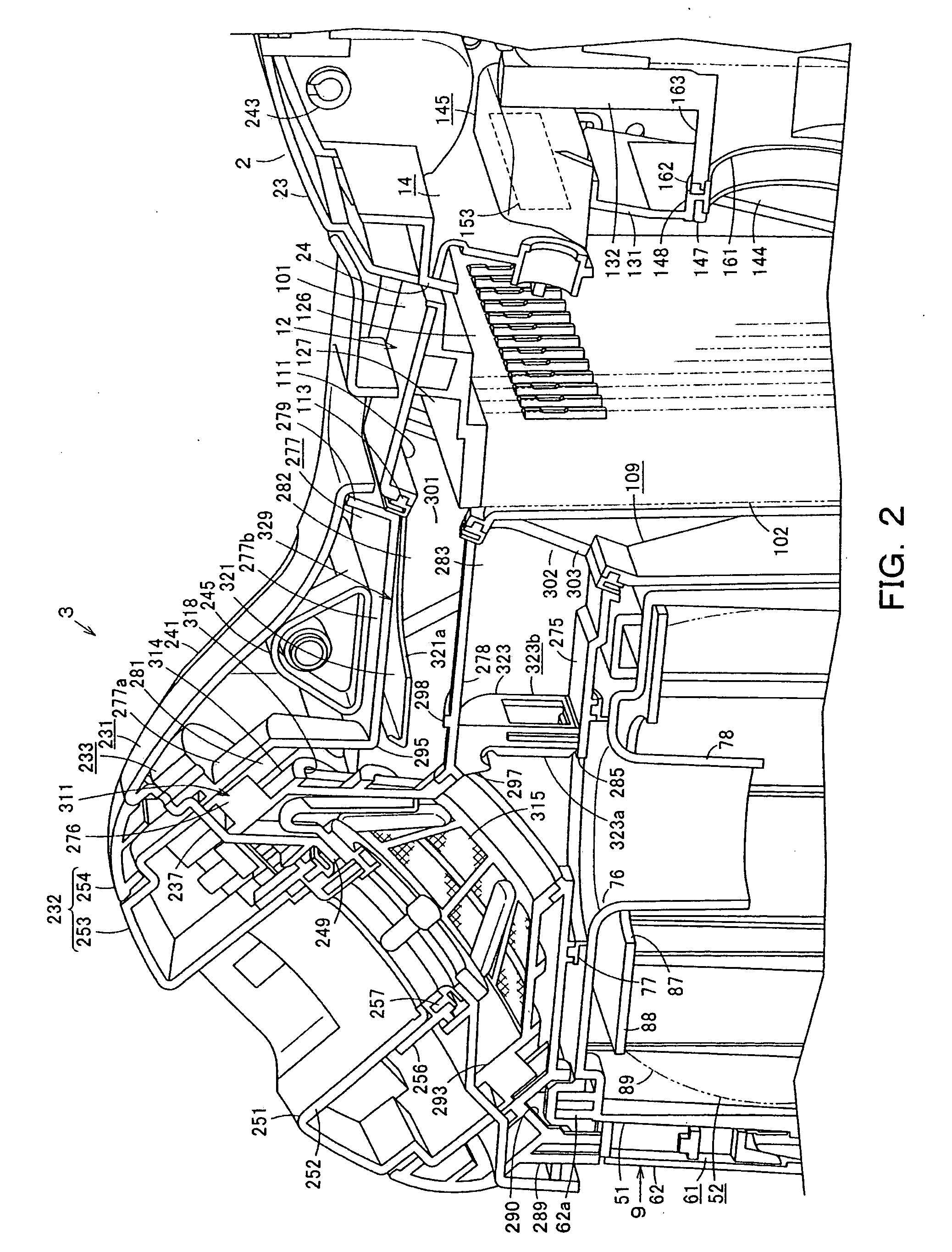
[0026]the present invention will be described below with reference to FIG. 1 to FIG. 10.

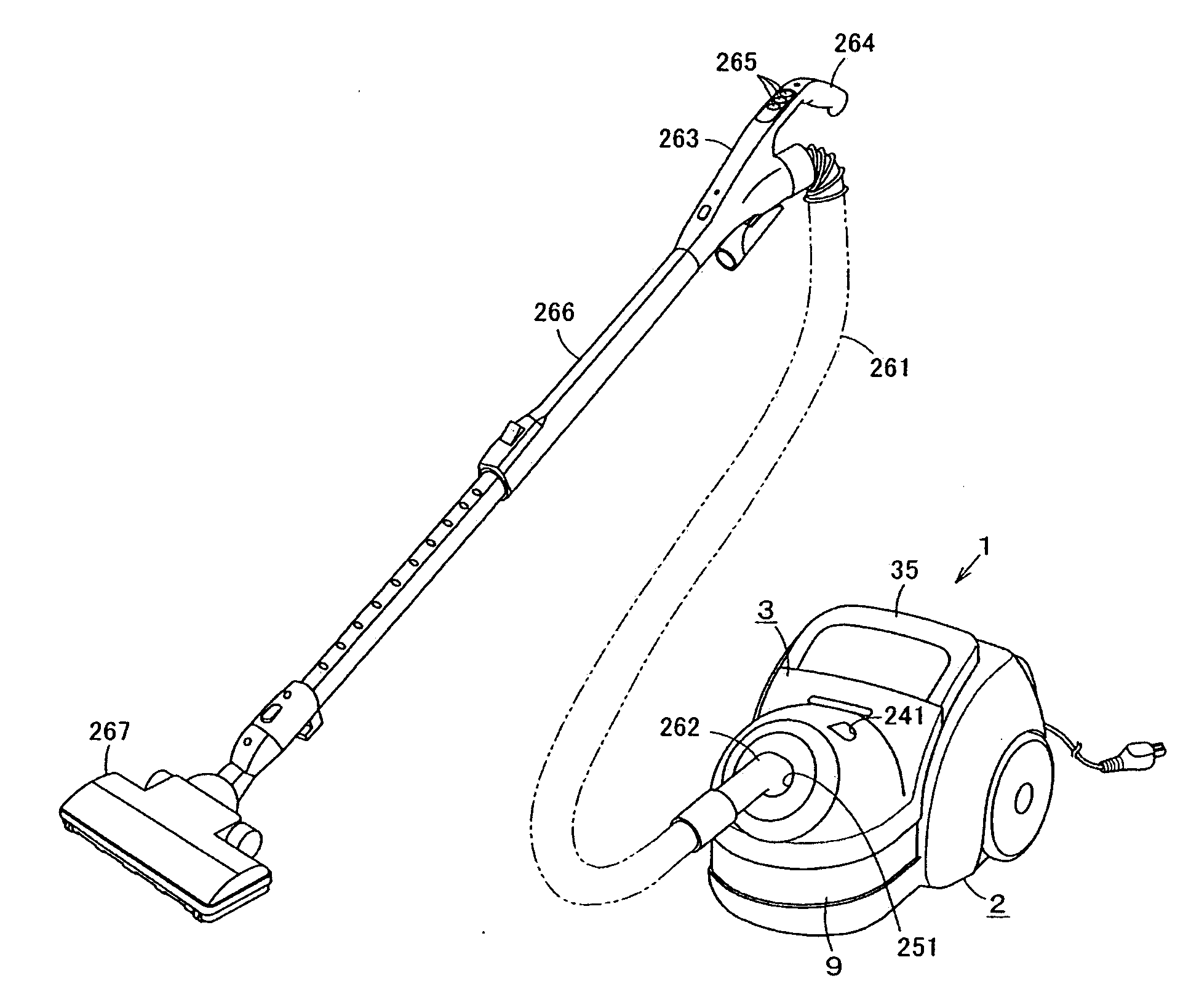
[0027]In FIG. 1, FIG. 3, FIG. 4 and FIG. 10, the reference numeral 1 denotes a vacuum cleaner main body, and the vacuum cleaner main body is a so-called canister type electric vacuum cleaner. The vacuum cleaner main body 1 has a main body case 2 and an openable / closable lid body 3 provided on the main body case 2.

[0028]The main body case 2 includes a lower case 5 formed in a long shape in a front and rear direction, and an upper case 6 provided to the upper side of the lower case 5. An electric blower chamber 8 with an electric blower 7 housed therein is formed at the rear portion of the main case body 2, and a recessed mount part 10 is formed at the front portion thereof, the recessed mount part 10 being a dust collecting unit attachment part on which a dust collecting unit 9 as a dust collecting unit being a main dust collecting unit is detachably mounted. A space 13, with which a filter 12 is ...


PUM


Abstract

In a suctioning state, even if the amount of dust trapped in a dust collecting unit in a main air passage is increased, air suctioned from a hose connection port is branched into a first half passage and reduction in the suction air amount can be suppressed. When the suctioning state is switched to a dust moving state by switch means, the dust trapped in a pleated filter is moved to the dust collecting unit, increase in the air passage resistance at the first half passage side caused by clogging of the pleated filter can be suppressed, and reduction in suction power over time can be suppressed. Since an upper air passage and lower air passage are provided in the lid body, the dust collecting unit is exposed with the lid body opened, whereby maintenance performance of the dust collecting unit is improved.

Description

INCORPORATION BY REFERENCE[0001]The present application claims priority under 35 U.S.C. § 119 to Japanese Patent Application No. 2007-095078 filed on Mar. 30, 2007. The content of the application is incorporation herein by reference in its entirety.FIELD OF THE INVENTION[0002]The present invention relates to an electric vacuum cleaner including a dust separator for separating dust from air.BACKGROUND OF THE INVENTION[0003]Conventionally, such kinds of electric vacuum cleaners have a constitution disclosed in Japanese Laid-Open Patent Publication No. 2005-211285, for example. That is, a conventional electric vacuum cleaner has a vacuum cleaner main body with an electric blower housed therein. A dust collecting cup, which is a dust collecting unit for collecting dust suctioned by driving the electric blower, is detachably provided in the vacuum cleaner main body. In the dust collecting cup, a dust separator is provided which communicates with a suction port and separates dust from air...

Claims


Application Information

Patent Timeline
Patent Type & Authority Applications(United States)
IPC IPC(8): A47L9/04
CPCA47L9/20A47L9/10A47L9/16
Inventor TANAKA, MASATOSHIMORISHITA, ATSUSHIEBE, KIYOSHI
Owner KK TOSHIBA
Learn More