Process and Device for Producing Threads, Especially for Boring Rods or the Like

a technology of grinding rods and grinding wheels, which is applied in the direction of turning equipment, milling equipment, worms, etc., can solve the problems of long metal chips, difficult control, and unsuitability of workpieces machined at higher speeds, and achieve the effect of increasing productivity

Inactive Publication Date: 2008-09-25
FMS DREHTECHN SCHAFFHAUSEN
View PDF13 Cites 15 Cited by
  • Summary
  • Abstract
  • Description
  • Claims
  • Application Information

AI Technical Summary

Benefits of technology

[0006]The basic object of the present invention is therefore to provide a process and a device for producing threads, with which the threads can be produced in one pass at high rpms and it is possible to greatly increase the productivity.
[0008]The process according to the present invention is based on a turning process with pitch-dependent feed and on the generation of the thread profile with the use of a rotating cam plate, which acts directly on the radial feed of the tool. The rotary motions of the workpiece and of the cam plate are synchronized now such that a thread with the desired pitch and direction is obtained from the relative motions of the rotating workpiece and the oscillating tool. The thread profile is determined by the shape of the cam. Depending on the stability of the tool, the threads are turned to the finished state up to a depth of thread of several mm, especially 3 mm, which represents an advantage of the process in terms of productivity, contrary to conventional thread cutting that does not belong to this class, in which the thread is generated by the longitudinal motion of the tool synchronously with the thread pitch with stepwise feed of the tool in the depth of thread, wherein a greater number of passes are necessary for this, depending on the profile size, and the number of passes is also determined by the nature of the workpiece and the quality of the tool.
[0012]The machining operation is divided by the present invention into a simple and proven mechanical generation of the thread profile and a linear, electronic synchronization for generating the thread pitch, as well as the use of the X slide of a lathe for generating the thread cone. The production of the cam shape for generating the thread profile can be carried out on conventional coordinate grinding machines or on milling machines. A changeover to different thread shapes is possible in a simple manner by replacing the cams and the part program. Because of the soft profile change of the disks (thread transitions with radii), it is possible to work with a spindle velocity of up to approximately 1,000 rpm.
[0013]It is possible due to the present invention to work at a relative rpm between 800 and 1,000 rpm, and the workpiece is, as a rule, usually rotated. The axial longitudinal feed of the tool relative to the workpiece is on the order of magnitude of 0.15 to 0.25 mm per revolution and preferably 0.2 mm per revolution. The thread is produced in one pass, and its precision can be readily checked. The thread profile can be produced by the present invention in one pass, so that separate roughing and finishing can be done away with. Perfect formation of a cutting is obtained. Due to the oscillation of the tool, a chip with increasing and decreasing thickness is formed during each revolution, and this chip breaks reliably at the thinnest point and facilitates removal from the drilled hole by blowing out or flushing out above all in case of internal threads.

Problems solved by technology

It is, furthermore, disadvantageous during thread cutting that long metal chips are formed, which are difficult to control.
Synchronization problems and hence profile distortions develop, which cause workpieces machined at higher velocities to be unfit for use.

Method used


Image

  • Process and Device for Producing Threads, Especially for Boring Rods or the Like
  • Process and Device for Producing Threads, Especially for Boring Rods or the Like
  • Process and Device for Producing Threads, Especially for Boring Rods or the Like

Examples


Embodiment Construction

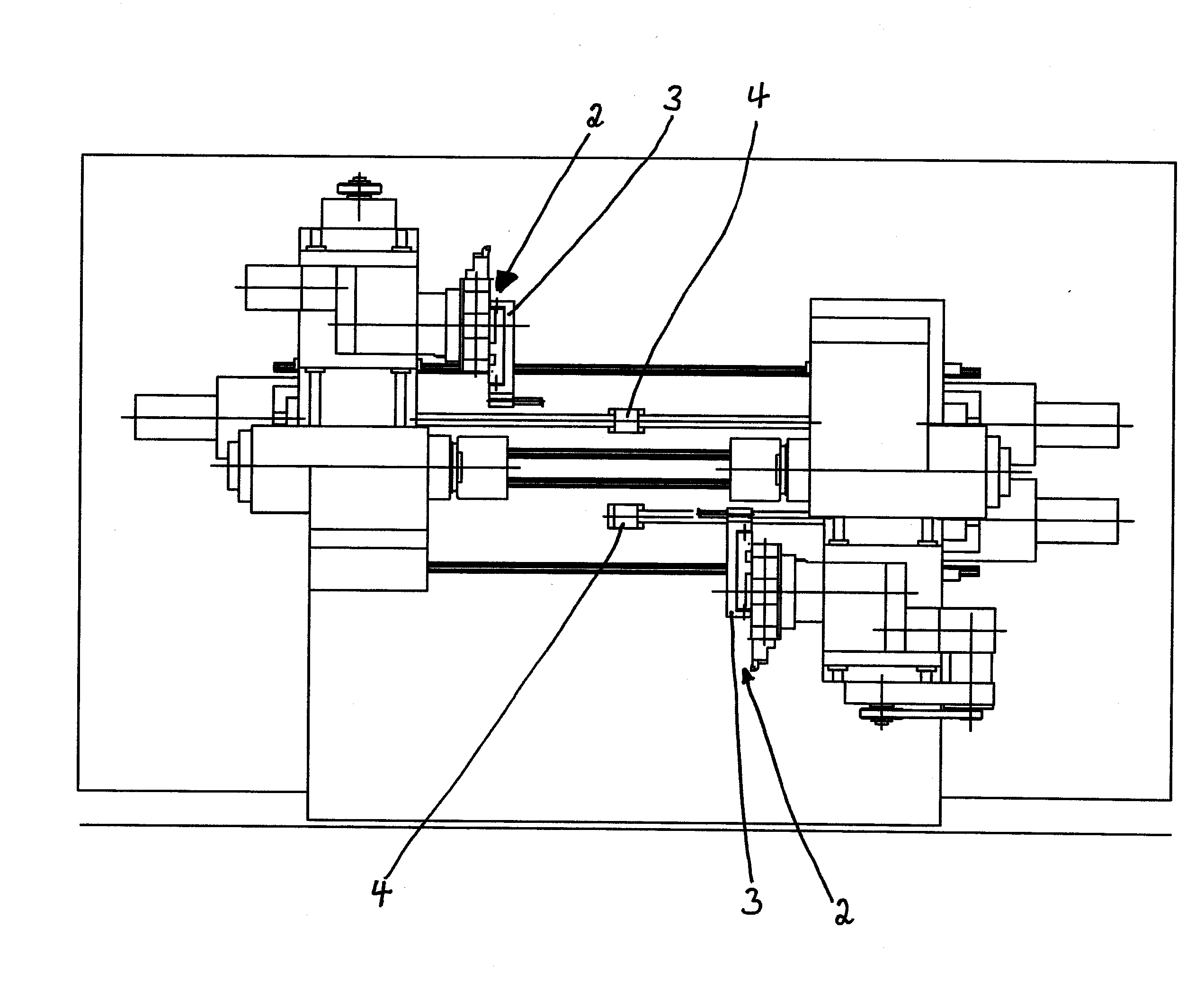
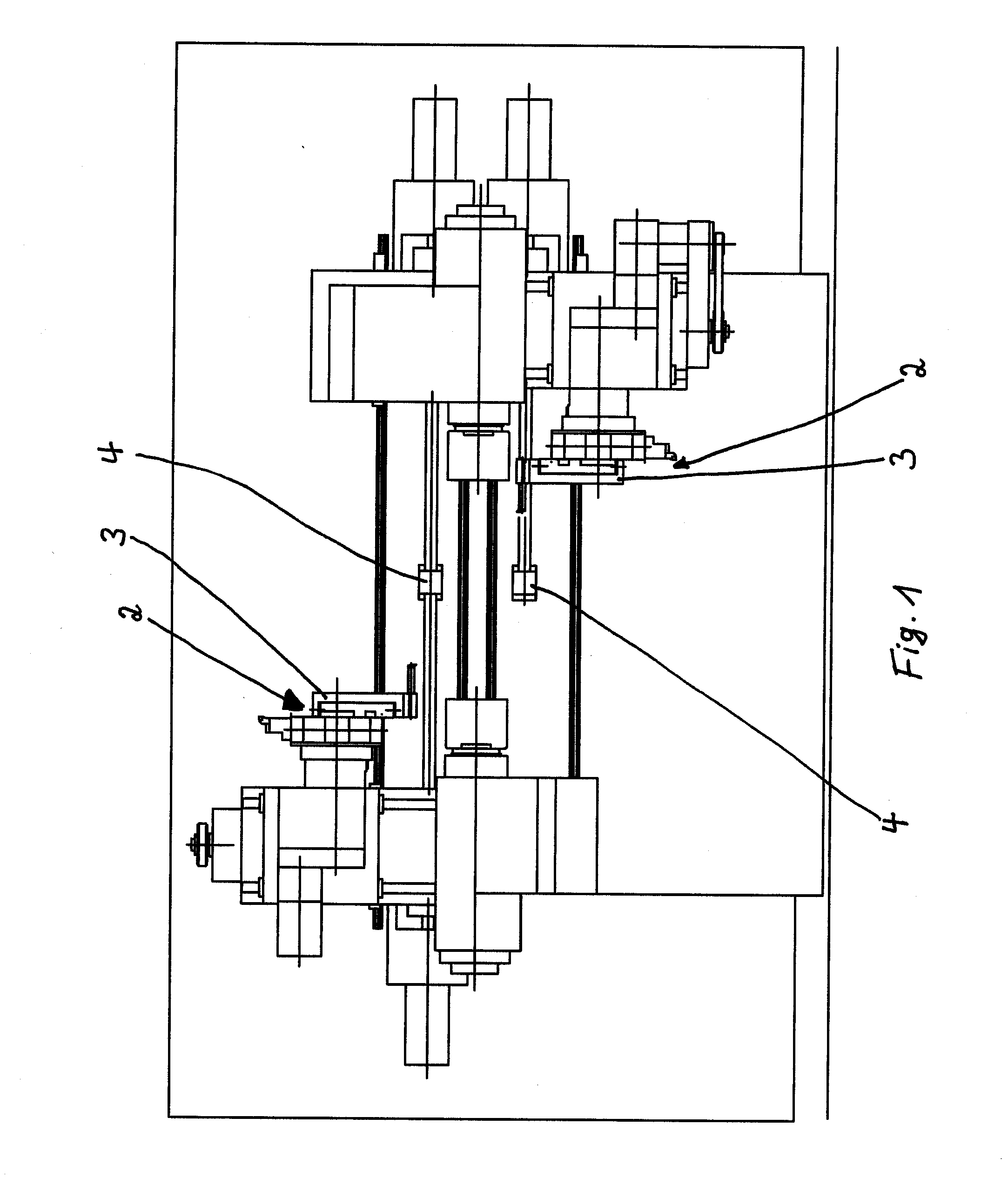
[0036]Referring to the drawings in particular, FIG. 1 shows a schematic view of a lathe 1 with two threading means 2, so that two threads can be turned simultaneously on this lathe. Lathe tools 4 are arranged on the threading means 2 at the cam part 3.

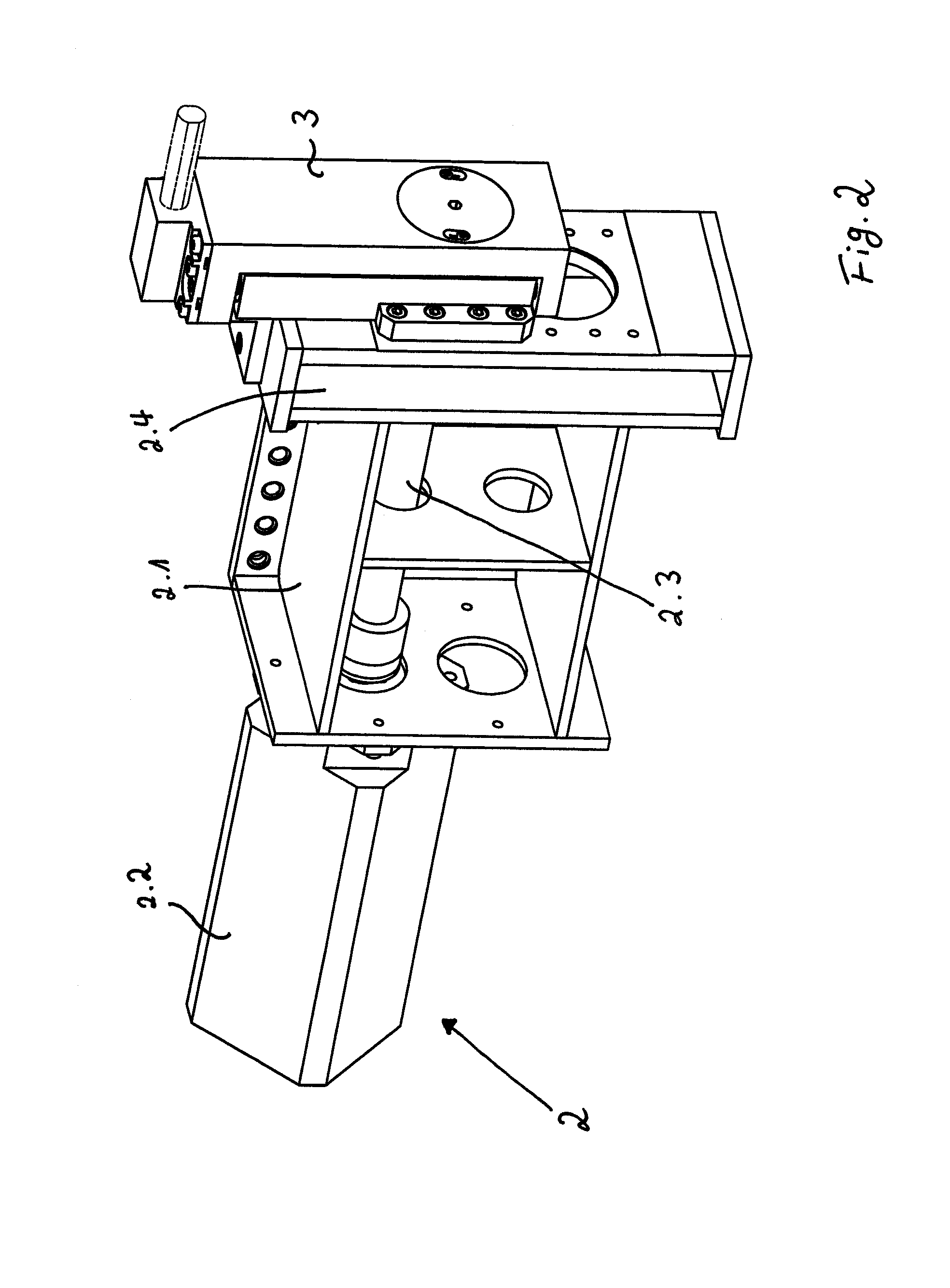
[0037]FIG. 2 shows a perspective view of a threading means 2 with a holding part 2.1, a motor operator acting as a drive motor 2.2, a drive shaft 2.3, a coupling unit 2.4, and the cam unit 3 proper.

[0038]FIG. 3 shows a longitudinal section through the threading means 2 according to FIG. 2, wherein the parts already named are named in the same manner.

[0039]The cam unit has a holding part 3. 1, which is rigidly connected to the coupling unit 2.4 and in which a cam plate 3.2 connected to the shaft 2.3 is rotatable. The holding part 3.1 carries, in a manner yet to be described more specifically, a slide 3.3, which can be displaced at right angles to the axis of the cam plate 3.2 and in the longitudinal direction of the holding part 3.1, an...


PUM

PropertyMeasurementUnit
Forceaaaaaaaaaa
Frequencyaaaaaaaaaa
Velocityaaaaaaaaaa

Abstract

The present invention proposes a process for producing threads, especially for boring rods or the like, wherein the workpiece and the lathe tool have a relative rotary motion at a high velocity about an axis of the workpiece and a relative longitudinal motion at a low velocity compared to the above velocity, and wherein an oscillating radial relative rotary motion is brought about, furthermore, between the lathe tool and the workpiece, wherein the radial oscillating motion is generated mechanically, the radial oscillating motion being synchronized, in particular, with the relative rotary motion. The present invention pertains, furthermore, to a device for producing threads by a means for generating the radial mechanical oscillating motion, where the radial oscillating motion is synchronized, in particular, with the relative rotary motion.

Description

CROSS REFERENCE TO RELATED APPLICATIONS[0001]This application is a United States National Phase application of International Application PCT / EP2006 / 007228 and claims the benefit of priority under 35 U.S.C. § 119 of German Application DE 10 2005 035 576.5 filed Jul. 29, 2005, the entire contents of which are incorporated herein by reference.FIELD OF THE INVENTION[0002]The present invention pertains to a process for producing threads, especially for boring rods or the like, wherein the workpiece and the lathe tool have a relative rotary motion at a high velocity about an axis of the workpiece and a relative longitudinal motion at a low velocity compared to the above velocity, and wherein a relative radial oscillating motion is, furthermore, brought about between the lathe tool and the workpiece, as well as to a device for producing threads, especially for boring rods or the like, with means for generating a relative rotary motion at a high velocity about the axis of a workpiece betwee...

Claims


Application Information

Patent Timeline
IPC IPC(8): B23C3/32B23B1/00
CPCB23B5/48B23B29/125B23B2260/02Y10T82/20B23G1/225B23G3/08Y10T409/300112B23G1/08
Inventor SCHIEMANN, HARRY
Owner FMS DREHTECHN SCHAFFHAUSEN
Why Eureka
Try Eureka