Catalytic converter system and element for diesel engines

a technology of catalytic converter and diesel engine, which is applied in the direction of machines/engines, mechanical equipment, separation processes, etc., can solve the problems of difficult application of catalytic converter devices to the exhaust system of two-stroke and four-stroke diesel engines, insufficient space around the engine for installation of a catalytic converter system, and relatively high lube oil consumption rate of engines. , to achieve the effect of low back pressure, easy removal for inspection and replacement, and efficient emissions reduction

Inactive Publication Date: 2008-09-25
MIRATECH GRP LLC
View PDF23 Cites 23 Cited by
  • Summary
  • Abstract
  • Description
  • Claims
  • Application Information

AI Technical Summary

Benefits of technology

[0007]The present invention provides an improved exhaust system which is well suited for use on diesel engines of the type discussed above. The inventive system satisfies the needs and alleviates the various problems already mentioned. The inventive system allows the integration of the diesel oxidation catalyst into the exhaust manifold system without significantly disturbing exhaust flow. In addition, the inventive system provides a large catalytic surface contact area which produces efficient emissions reduction while maintaining a low back pressure. Moreover, the inventive system does not require any significant amount of additional space, does not block the engine access covers, and does not interfere with engine maintenance. Also, the catalytic elements of the inventive system are easily removable for inspection and replacement without dismantling any portion of the exhaust manifold.

Problems solved by technology

The application of catalytic converter devices to the exhaust systems of two-stroke and four-stroke diesel engines has been difficult for several reasons.
In many cases, particularly in locomotive applications, there is not sufficient space around the engine for installation of a catalytic converter system.
Further, these engines have a relatively high lube oil consumption rate.
In addition, it is difficult in locomotive and other applications to remove the exhaust manifolds from the engines due to a lack of sufficient overhead space for the lifting equipment.
Also, the back pressure limits of the turbocharged diesel engines are typically very low.

Method used


Image

  • Catalytic converter system and element for diesel engines
  • Catalytic converter system and element for diesel engines
  • Catalytic converter system and element for diesel engines

Examples


embodiment 20

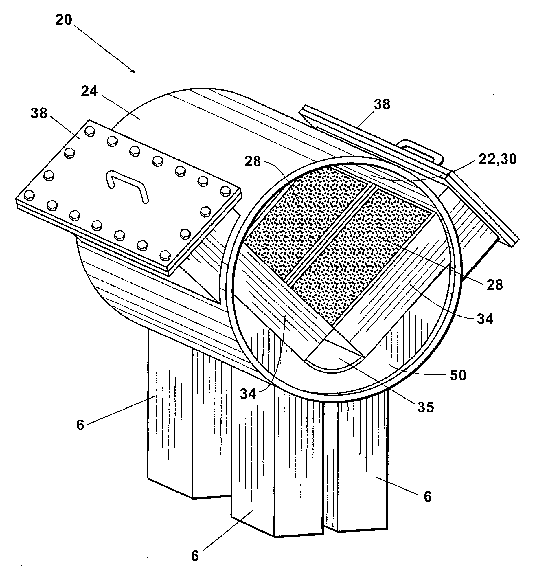
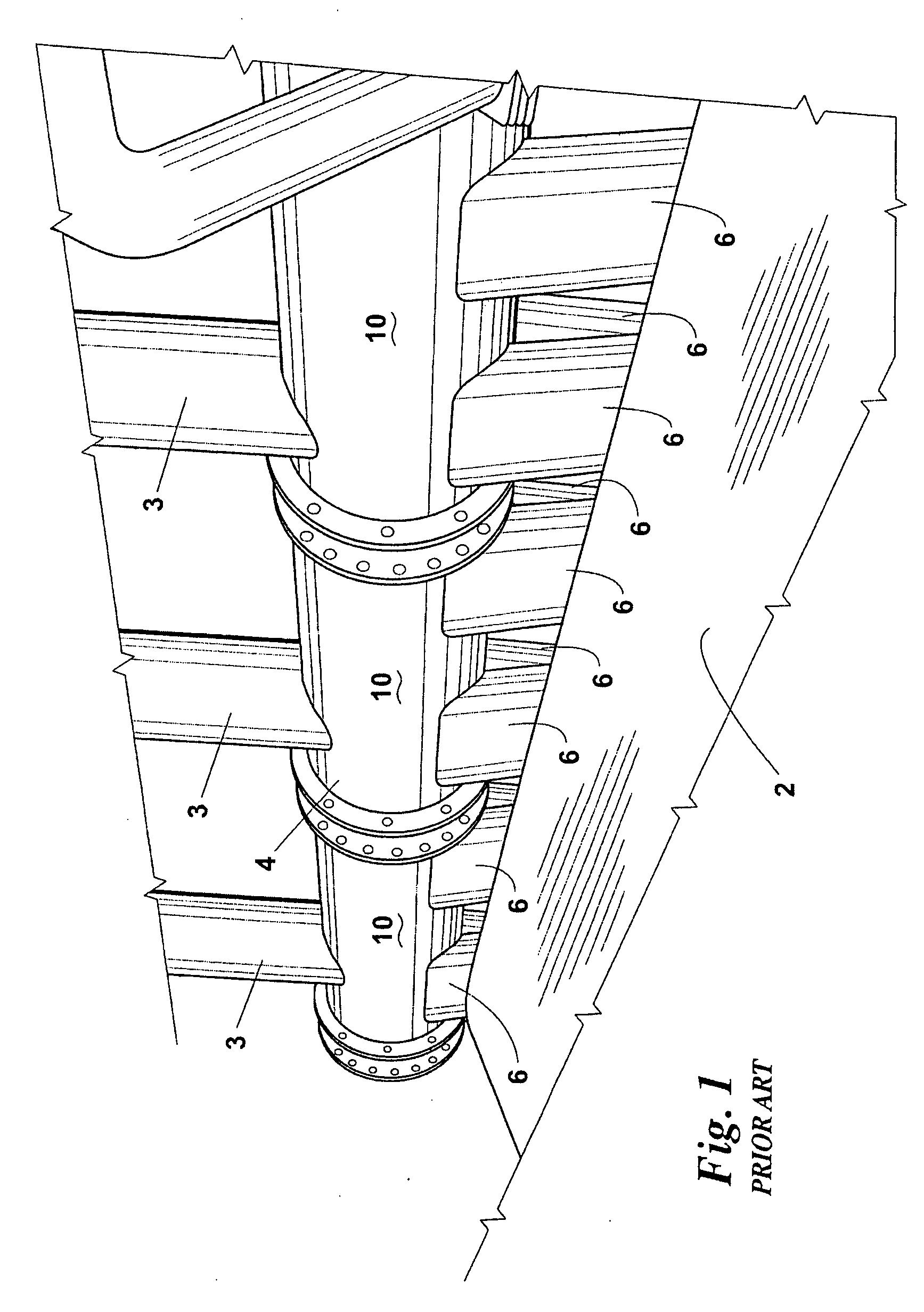
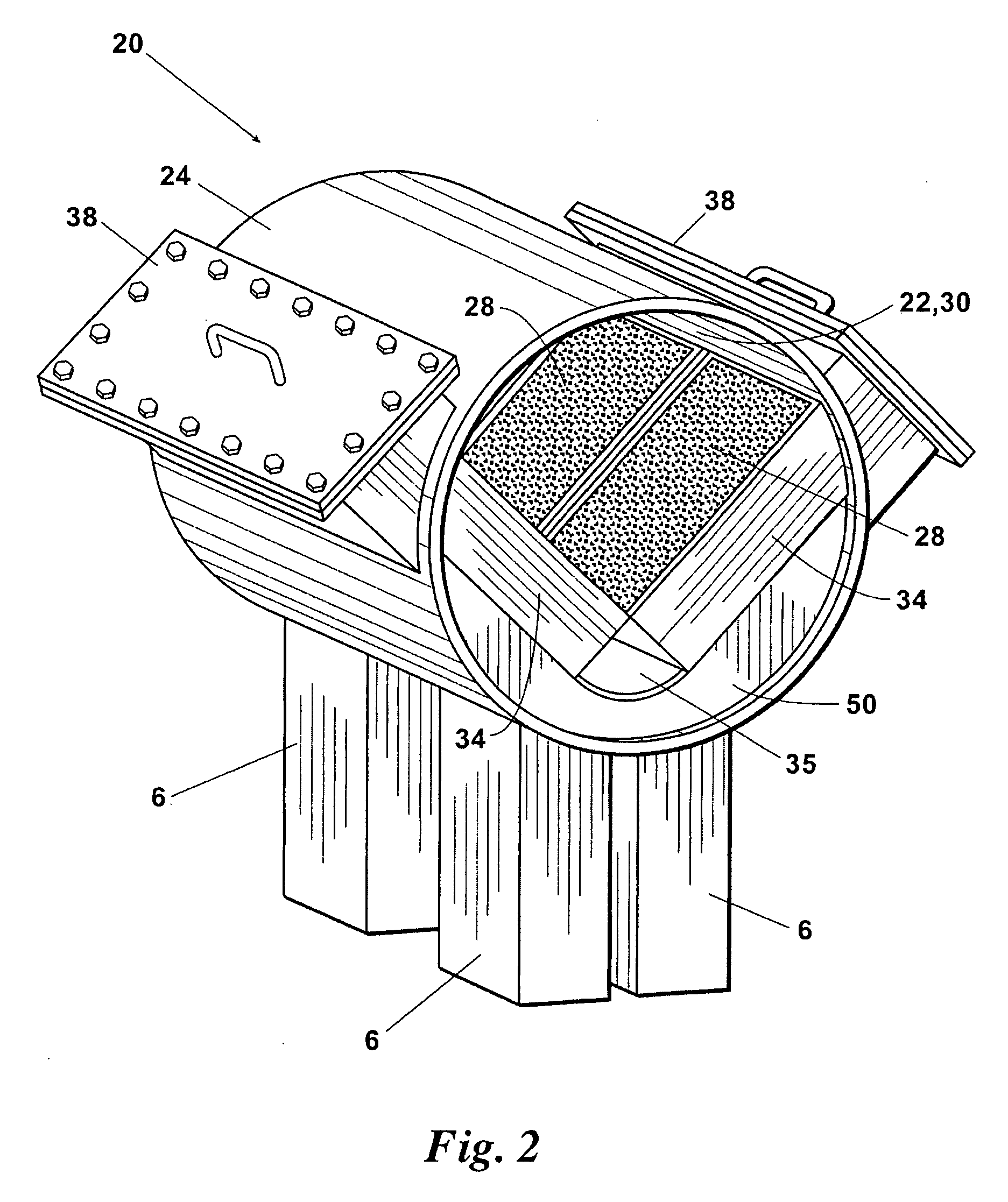
[0042]An embodiment 20 of an improved overhead exhaust manifold segment for a diesel engine exhaust system is depicted in FIGS. 2 and 3. The inventive manifold segment 20 improves and replaces the overhead manifold segments 10 presently used in the overhead exhaust systems of roots-blown, turbocharged, or other types of diesel engines.

[0043]The inventive manifold segment 20 comprises: a longitudinal interior passage 22; a longitudinal outer cylindrical wall 24 which surrounds the internal passage 22; a plurality of (preferably at least two and most preferably four) openings 26 in the bottom of the cylindrical wall 24 which are in fluid communication with the upper outlet ends of the manifold legs 6 extending from the engine cylinder exhaust ports; and one or more (preferably a plurality of) catalytic converter elements 28 which are removably insertable in the longitudinal passage 22 such that substantially all of the engine exhaust gas received in the overhead exhaust manifold via t...

embodiment 60

[0056]FIGS. 4-6 illustrate another inventive embodiment 60 of a catalytic converter element which can be used in the inventive catalytic converter system as an alternative to the converter element 28 described above. The inventive catalytic converter element 60 is similar to the catalytic converter element 28 except that the catalytic converter element 60 includes additional features which further assist in retaining the substrate 62 within the outer retaining band or frame 64 and therefore assist in preventing the substrate 62 from becoming loose or breaking free because of prolonged exposure to the exhaust pressure pulses produced by the diesel engine.

[0057]The additional improvements embodied in the inventive catalytic converter element 60 include: (a) an upper retaining lip 66 which extends centrally along the length of the interior side of the upper horizontal segment 68 of the retaining band or frame 64 and projects a short distance into the horizontal top side edge 70 of the ...


PUM

PropertyMeasurementUnit
frictional resistanceaaaaaaaaaa
speedaaaaaaaaaa
temperatureaaaaaaaaaa

Abstract

An improved exhaust system and catalytic converter element for a diesel engine wherein the improvement comprises: holding means for restricting the movement of catalytic converter elements in an overhead exhaust manifold; an improved catalytic converter element having at least one retaining rod extending through the catalyst substrate and/or having at least one retaining lip projecting into the substrate; a stabilizer projecting from the cover for the element insertion slot for receiving an end portion of the catalytic converter element to restrict the movement of the converter element in the exhaust manifold; perforated flow distribution elements provided upstream of the catalytic converter elements; and/or vertical coupling manifolds which each receive exhaust from a pair of engine cylinders and then deliver the combined exhaust stream to a separate one of the inlet openings in the bottom of the overhead exhaust manifold.

Description

[0001]This is a continuation-in-part application of U.S. patent application Ser. No. 11 / 311,868, filed Jan. 19, 2005, which application is incorporated herein in its entirety by reference.FIELD OF THE INVENTION[0002]The present invention relates to catalytic converters and catalytic converter elements for diesel engines having overhead exhaust manifold systems.BACKGROUND OF THE INVENTION[0003]Two-stroke and four stroke medium speed diesel engines such as those manufactured by Electromotive Diesels (EMD) of LaGrange, Ill. (formerly a division of General Motors) are used in locomotives, in power generating systems, and in marine propulsion applications. An example of one common type of diesel engine, depicted in FIG. 1, is an EMD 645 E-16 two-stroke, “roots-blown” engine having an exhaust system which comprises an elongated overhead exhaust manifold 4 which runs horizontally above the centerline of the engine 2. The overhead manifold 4 receives exhaust gas via a series of pairs of opp...

Claims


Application Information

Patent Timeline
Patent Type & Authority Applications(United States)
IPC IPC(8): F01N3/10
CPCF01N3/2839F01N2450/30F01N2450/24F01N13/10
Inventor NEWBURRY, DONALD M.URIBE, JUAN CARLOSTHOMPSON, JOSHUA NEILLAMBERT, DONALD CHRISTOPHERFARRINGTON, DANIEL ALANSTEPHENS, RACHEL ELIZABETHSARTAIN, JOHN W.
Owner MIRATECH GRP LLC
Why Eureka
Try Eureka