
Analyte measuring device

a technology of analyte and measuring device, which is applied in the field of biointerface membranes, can solve the problems of loss of function, inability to provide data safely and reliably for long periods of time, and loss of function of current used devices

Inactive Publication Date: 2008-09-18
DEXCOM INC
View PDF21 Cites 783 Cited by
  • Summary
  • Abstract
  • Description
  • Claims
  • Application Information

AI Technical Summary

Benefits of technology

[0017]The biointerface membranes, devices including these membranes, and methods of use of these membranes according to the preferred embodiments allow for long term protection of implanted cells or drugs, as well as for obtaining continuous information regarding, for example, glucose levels of a host over extended periods of time. Because of these abilities, the biointerface membranes of the preferred embodiments can be extremely useful in implantable devices for the management of transplant patients, diabetic patients, and patients requiring frequent drug treatment.
[0110]The devices of the preferred embodiments allow continuous information regarding, for example, glucose levels. Such continuous information enables the determination of trends in glucose levels, which can be extremely desirable in the management of diabetic patients.

Problems solved by technology

Despite the increasing number of individuals diagnosed with diabetes and recent advances in the field of implantable glucose monitoring devices, currently used devices are unable to provide data safely and reliably for long periods of time (for example, months or years).
With reference to conventional devices that can be implanted in tissue, a disadvantage of these devices is that they tend to lose their function after the first few days to weeks following implantation.
While not wishing to be bound by any particular theory, it is believed that this loss of function is due to the lack of direct contact with circulating blood to deliver sample to the tip of the probe of the implanted device.
Because of these limitations, it has previously been difficult to obtain continuous and accurate glucose level measurements.
A disadvantage of cell-impermeable membranes is that they often stimulate a local inflammatory response, called the foreign body response (FBR) that has long been recognized as limiting the function of implanted devices that require solute transport.
Previous efforts to overcome this problem have been aimed at increasing local vascularization at the device-tissue interface, but have achieved only limited success.
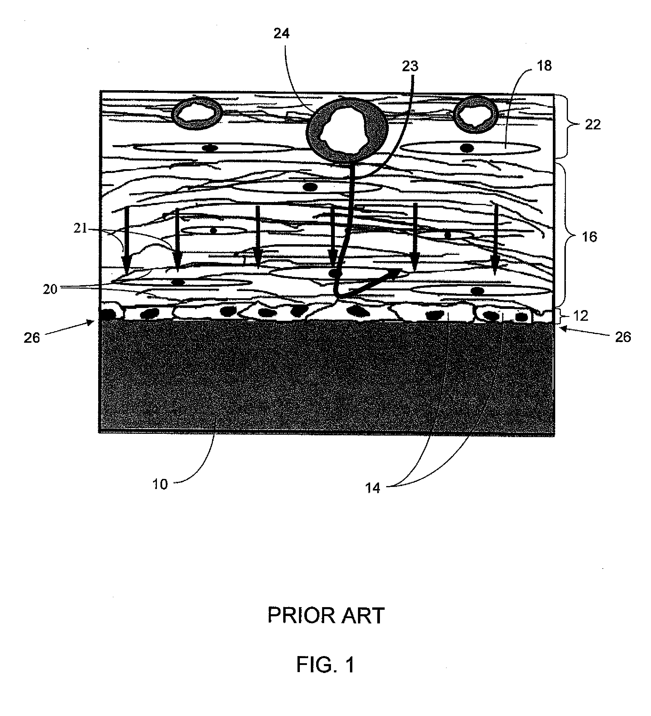
This has led to widely supported speculation that poor transport of molecules across the device-tissue interface 26 is due to a lack of vascularization near the interface.
Previous efforts to overcome this problem have been aimed at increasing local vascularization at the device-tissue interface, but have achieved only limited success.
For example, when applied to an implantable glucose-measuring device, both glucose and its phosphorylated form do not readily transit the cell membrane.
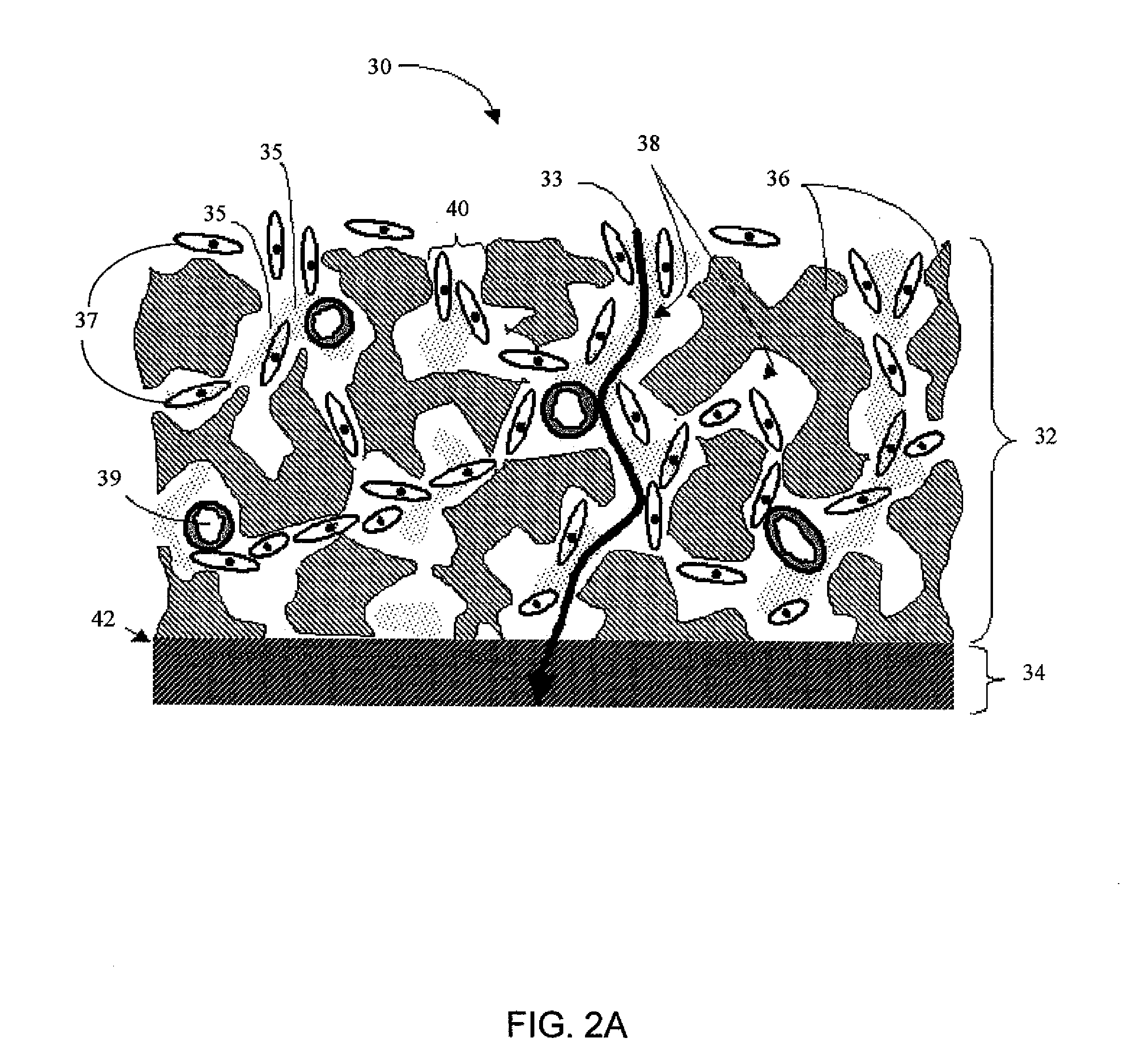
However, it has been observed by the inventors that once the monolayer of cells (barrier cell layer) is established adjacent to a membrane, increasing angiogenesis is not sufficient to increase transport of molecules such as glucose and oxygen across the device-tissue interface 26.
Despite recent advances in the field of implantable glucose monitoring devices, presently used devices are unable to provide data safely and reliably for long periods of time (e.g. months or years).
Unfortunately, probes that are placed directly into the vasculature put the recipient at risk for thrombophlebosis, thromboembolism, and thrombophlebitis.
Similarly, in order to be effective, the probe consumes some oxygen and glucose, but not enough to perturb the available glucose which it is intended to measure; subcutaneously implanted probes often reside in a relatively stagnant environment in which oxygen or glucose depletion zones around the probe tip can result in erroneously low measured glucose levels.
Finally, the probe can be subject to “motion artifact” because the device is not adequately secured to the tissue, thus contributing to unreliable results.

Method used


Image

  • Analyte measuring device
  • Analyte measuring device
  • Analyte measuring device

Examples


example 1

[0319]The polyurethanes are preferably prepared as block copolymers by solution polymerization techniques as generally described in Lyman, J. Polymer Sci. 45:49 (1960). Specifically, a two-step solution polymerization technique is used in which the poly(oxyethylene) glycol is first “capped” by reaction with a diisocyanate to form a macrodiisocyanate. The macrodiisocyanate is then coupled with a diol (or diamine) and the diisocyanate to form a block copolyetherurethane (or a block copolyurethaneurea). The resulting block copolymers are tough and elastic and can be solution-cast in N,N-dimethylformamide to yield clear films that demonstrate good wet strength when swollen in water.

[0320]In particular, a mixture of 8.4 g (0.006 mol), poly(oxyethylene) glycol (CARBOWAX® 1540, Union Carbide), and 3.0 g (0.012 mol) 4,4′-diphenylmethane diisocyanate in 20 mL dimethyl sulfoxide / 4-methyl-2-pentanone (50 / 50) is placed in a three-necked flask equipped with a stirrer and condenser and protected ...

example 2

[0322]As previously described, the electrolyte layer, the membrane layer closest to the electrode, can be coated as a water-swellable film. This example illustrates a coating comprising a polyurethane having anionic carboxylate functional groups and hydrophilic polyether groups and polyvinylpyrrolidone (PVP) that can be cross-linked by carbodiimide.

[0323]A coating preparation is prepared comprising a premix of a colloidal aqueous dispersion of particles of a urethane polymer having a polycarbonate-polyurethane (PC-PU) backbone containing carboxylate groups and the water-soluble hydrophilic polymer, PVP, which is crosslinked by the addition of the cross-linking agent just before production of the coated membrane. Example coating formulations are illustrated in Table 1.

TABLE 1ABCDryDryDryWeightWeightWeightWeight% SolidsWeight% SolidsWeight% SolidsPremixPVP148664816020PC-PV2260912488720070Cross-Linking AgentCarbodiimide3631052010Totals3141003221003801001Aqueous solution containing 12.5...

example 3

[0326]The following procedure was used to determine the amount of enzyme to be included in the enzyme layer. It is to be understood that the preferred embodiments are not limited to the use of this or a similar procedure, but rather contemplates the use of other techniques known in the art.

[0327]A starting glucose oxidase concentration of 2×10⁻⁴ M was calculated from the enzyme weight and the final volume of the enzyme layer. Thereafter, a series of eight additional membrane formulations was prepared by decrementing enzyme concentration in 50% steps (referred to as a change of one “half loading”) down to 7.8-7 M. Sensor responses were then collected for this range of enzyme loadings and compared to computer-simulated sensor outputs. The simulation parameter set used included previously determined membrane permeabilities and the literature mechanisms and kinetics for glucose oxidase. See, e.g. Rhodes et al., Anal. Chem., 66:1520-1529 (1994).

[0328]There was a good match of real-to-sim...


PUM

PropertyMeasurementUnit
pore sizeaaaaaaaaaa
timeaaaaaaaaaa
diametersaaaaaaaaaa

Abstract

An implantable analyte-measuring device including a membrane adapted to promote vascularization and / or interfere with barrier cell layer formation. The membrane includes any combination of materials, architecture, and bioactive agents that facilitate analyte transport to provide long-term in vivo performance of the implantable analyte-measuring device.

Description

CROSS-REFERENCE TO RELATED APPLICATIONS[0001]This application is a division of application Ser. No. 10 / 846,150, filed May 14, 2004, which is a continuation-in-part of application Ser. No. 10 / 647,065, filed Aug. 22, 2003, which claims the benefit of priority under 35 U.S.C. § 119(e) to Provisional Application No. 60 / 472,673, filed May 21, 2003, and is a continuation-in-part of application Ser. No. 09 / 447,227, filed Nov. 22, 1999, which is a division of application Ser. No. 08 / 811,473, filed Mar. 4, 1997, now U.S. Pat. No. 6,001,067. Application Ser. No. 10 / 846,150 claims the benefit of priority under 35 U.S.C. § 119(e) to Provisional Application No. 60 / 544,722, filed Feb. 12, 2004. All above-referenced prior applications are incorporated by reference herein in their entirety.FIELD OF THE INVENTION[0002]The present invention relates generally to biointerface membranes that can be utilized with implantable devices, such as devices for the detection of analyte concentrations in a biolog...

Claims


Application Information

Patent Timeline
Patent Type & Authority Applications(United States)
IPC IPC(8): A61B5/05A61B5/00A61K9/22A61L31/10A61L31/14A61L31/16C12Q1/00
CPCA61B5/14532A61B5/14865A61B5/1495A61L31/10C12Q1/006A61L31/146A61L31/16A61L2300/00A61L31/14B33Y80/00
Inventor SHULTS, MARK C.BRAUKER, JAMES H.CARR-BRENDEL, VICTORIATAPSAK, MARK A.MARKOVIC, DUBRAVKAUPDIKE, STUART J.RHODES, RATHBUN K.
Owner DEXCOM INC
Learn More