
Development device, process cartridge, and image formation apparatus

a development device and process cartridge technology, applied in electrographic process devices, instruments, optics, etc., can solve the problems of reducing the volume of a metal shaft, reducing the rigidity of a magnetic roller, and making the density of an image non-uniform, so as to achieve good stability and high quality , the effect of low deflection

Inactive Publication Date: 2008-09-18
RICOH KK
View PDF3 Cites 10 Cited by
  • Summary
  • Abstract
  • Description
  • Claims
  • Application Information

AI Technical Summary

Benefits of technology

[0010]An object of the present invention is to provide a durable development device which can form images in high quality with a little deflection of the magnetic roller without increasing the rigidity thereof and the rotation torque of the development sleeve, as well as to provide a process cartridge including such a development device and an image formation apparatus including such a process cartridge.

Problems solved by technology

However, it is difficult to downsize the development roller with its magnetic force and rigidity maintained high because to increase the magnetic force, it is effective to increase volume of magnets but at the same time the increase in volume of magnets results in reducing the volume of a metal shaft for holding the development roller, causing a reduction in the rigidity of a magnetic roller.
This may cause various problems such that a deflection occurs on the magnetic roller when the rigidity of the magnetic roller is not sufficient, or that a variation in magnetic flux density makes the amount of developer nonuniform in a longitudinal direction and makes density of an image nonuniform accordingly.
Furthermore, with a large deflection thereon, the magnetic roller may get in contact with the development sleeve, causing an increase in rotation torque, or even worse, destructing the magnetic roller.
However, there are some drawbacks in the rotatable member that it makes the structure of the device more complex and increases the size and production cost thereof.
Accordingly, it is not suitable for a small-size development roller.
Another problem is that an increase in torque of the development sleeve is unavoidable when the development sleeve is made in contact with the magnetic roller.
However, the development device is not for the two-component magnetic brush development; therefore, it cannot achieve great effects even if applied therefor.

Method used


Image

  • Development device, process cartridge, and image formation apparatus
  • Development device, process cartridge, and image formation apparatus
  • Development device, process cartridge, and image formation apparatus

Examples


first embodiment

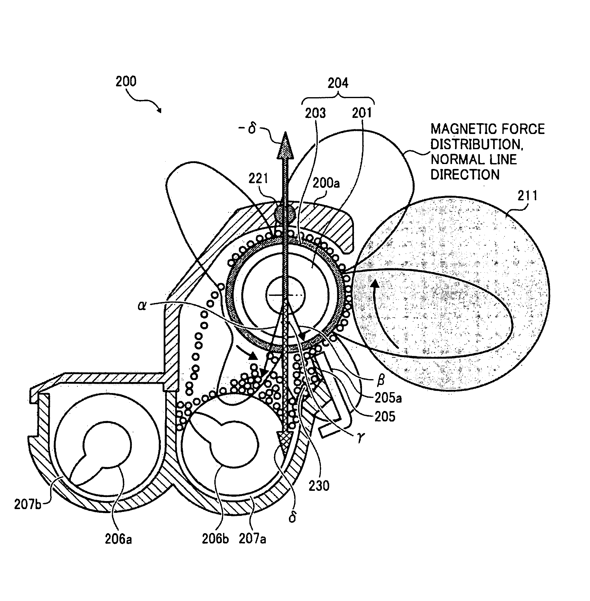
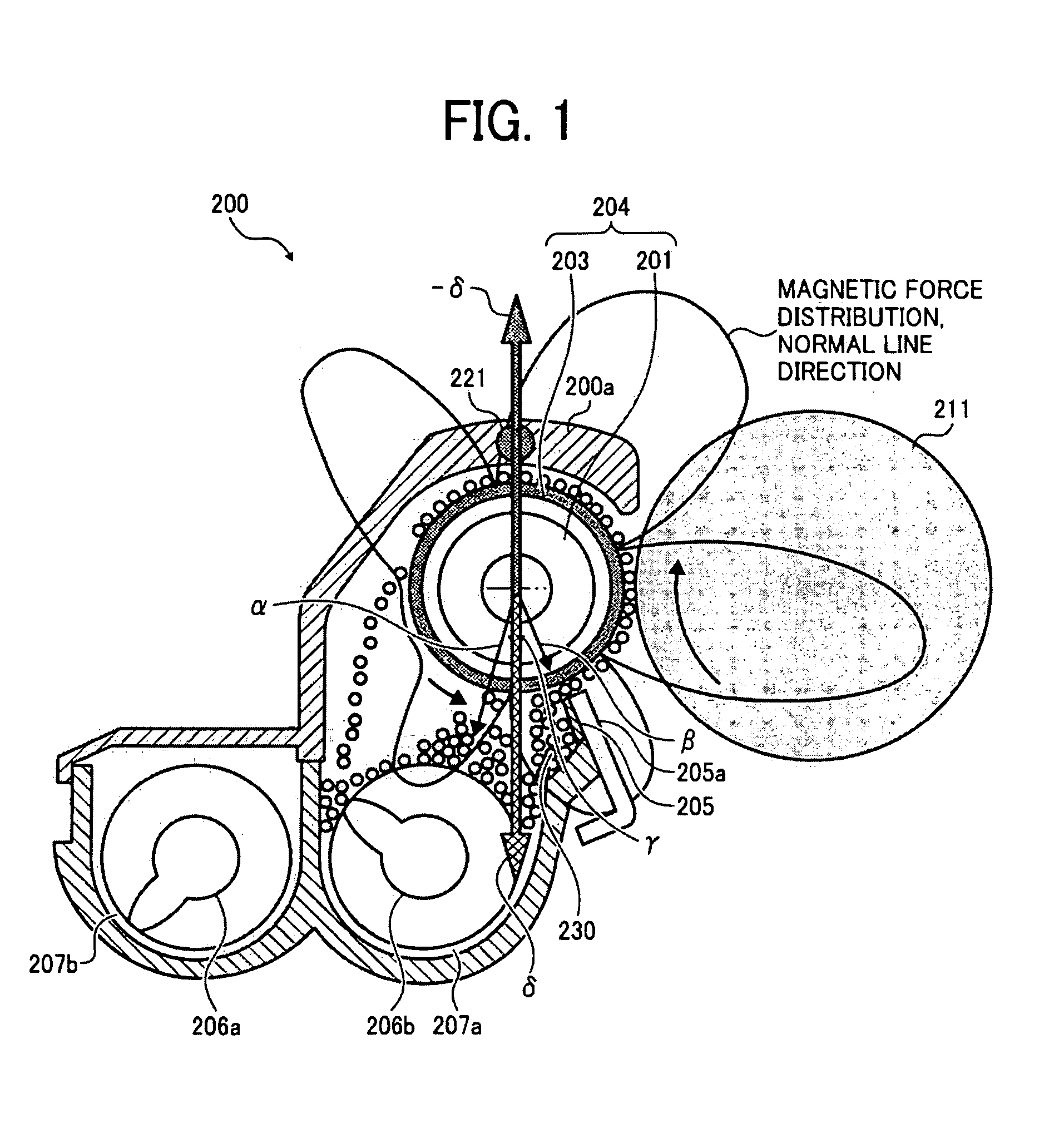
[0028]Hereinafter, the development device of the first embodiment will be described with reference to FIG. 1. FIG. 1 shows a development device 200 according to the first embodiment of the present invention. The development device 200 is configured to comprise a development roller 204 as a developer support body which includes a metal sleeve 203 (to rotate counterclockwise in the drawing) as a non-magnetic hollow body containing a fixed magnetic roller 201 as a magnetic field generator to absorb a developer 230 on its outer surface by a magnetic force of the magnetic roller 201.

[0029]The developer 230 is made of evenly distributed magnetic particles and toner particles and is attracted into the surface of the development roller 204 by the magnetic force of the development roller 204 and moved by the rotation of the sleeve 203 while circulated between developer tanks 207a, 207b by agitation of two agitation screws 206a, 206b. A magnetic plate 205a of a restriction blade 205 limits th...

second embodiment

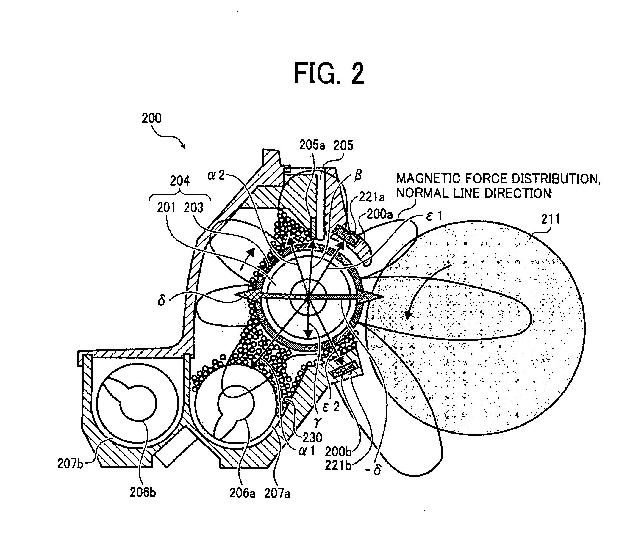
[0037]Next, the second embodiment of the present invention will be described with reference to FIG. 2. In the drawing, the same components as those in FIG. 1 are given the same numeric codes. The present embodiment differs from the first embodiment in that two magnetic metal members are disposed on the housing 200a, that the sleeve 203 of the development roller 204 is rotated clockwise and the photoconductive drum 211 is rotated counterclockwise and that the restriction blade for the developer 230 is disposed over the development roller 204 unlike that disposed thereunder in the first embodiment. A large amount of the developer 230 is distributed unevenly on an upstream portion near the agitation screws 206a, 206b and the restriction blade 205. The magnetic metal plate 205a of the restriction blade (doctor blade) 205 is disposed over the sleeve 202 and the magnetic roller 201.

[0038]On the center of the magnet roller 201 acts a magnetic force δ as a sum of a magnetic force of a lower...

third embodiment

[0041]The third embodiment of the present invention will be described with reference to FIGS. 3A, 3B. The same components of the development device as those in the first embodiment are given the same numeric codes.

[0042]FIG. 3A shows an example where the developer is attached with a high magnetic flux density (magnetic distribution from the magnetic roller 201 to left-downward in the drawing) in a portion from the agitation screws 206a, 206b to the development roller 204. In this case, a larger amount of the developer 230 is attached thereon, and a higher magnetic attraction acts on the magnetic roller 201 from the developer 230 accordingly, compared with that in the first embodiment. As a result, a larger combined force δ acts on the magnetic roller 201. In order to prevent this from occurring, the magnetic metal member need be increased in volume or the material thereof need be of a high magnetic permeability. However, the former is unfeasible considering the layout of the device,...


PUM


Abstract

A development device includes a developer support body including a non-magnetic hollow body which contains a magnetic field generator and attracts a developer onto an outer surface by a magnetic force of the magnetic field generator, a magnetic member being disposed around the magnetic field generator and exerting a magnetic force on the magnetic field generator, and an anti-deflection magnetic field generator being provided around the hollow body and exerting a magnetic force on the magnetic field generator to prevent a deflection of the magnetic field generator by negating at least one of the magnetic force of the magnetic member and a gravitational force due to empty weight of the magnetic field generator.

Description

CROSS REFERENCE TO RELATED APPLICATION[0001]The present application is based on and claims priority from Japanese Patent Application No. 2007-066478, filed on Mar. 15, 2007, the disclosure of which is hereby incorporated by reference herein in its entirety.BACKGROUND OF THE INVENTION[0002]1. Field of the Invention[0003]The present invention relates to a development device, a process cartridge, and an image formation apparatus for use in a copier, a facsimile machine, a printer, or the like. Particularly, it relates to a development device which includes an image support body to support magnetic particles and a magnetic particle support body and carries the magnetic particles to an develop area formed by the image support body and magnetic particle support body facing each other with a spacing, to develop an electrostatic latent image on the image support body to a toner image. It also relates to a process cartridge including the development device, and an image formation apparatus u...

Claims


Application Information

Patent Timeline
Patent Type & Authority Applications(United States)
IPC IPC(8): G03G15/09
CPCG03G2215/0648G03G15/0921
Inventor KOETSUKA, KYOHTAHATTORI, TADAAKITAKANO, YOSHIYUKIKAMIYA, NORIYUKIOHSAWA, MASAYUKITERASHIMA, MIEKOABE, HIROYAINNAMI, TAKASHI
Owner RICOH KK
Learn More