Pole support for an upright pole

Inactive Publication Date: 2008-09-18
ZHEJIANG YOTRIO GRP CO LTD
View PDF6 Cites 36 Cited by
  • Summary
  • Abstract
  • Description
  • Claims
  • Application Information

AI Technical Summary

Benefits of technology

[0013]The design of the pole support according to the invention realizes a functional separation. Accordingly, the pole base essentially serves the purpose of defining a support area of the pole support with respect to the floor, which is in particular based on the lateral, i.e., horizontal, extension of the pole base. Moreover, the pole support is connected to or integrated in the pole base. The mass of the pole base can be comparatively low. In contrast, the mass required to stabilize the pole base on the floor is essentially applied with the weight, the mass of which acts upon the pole base. The action of the weight on the pole base has a positive effect on the center of gravity of the pole support and as a result on the whole set-up of the pole support including the inserted umbrella. Based on the selected mass and position of the weight with respect to the pole base, the center of gravity of the whole set-up can be placed across the center of the pole base to prevent tilting.
[0028]In another preferred embodiment of the pivot bearing described above, the bearing unit could comprise a brake and / or locking mechanism, preferably operable by means of a foot control protruding over the weight. Said foot control could preferably be connected to the brake and locking mechanism with a telescopic arm that can be locked at different lengths. Said adjustability of the telescopic arm would allow the convenient adjustment of the foot control at different heights of the weight.

Problems solved by technology

The disadvantage of pole supports according to prior art is that they are heavy to be able to fulfill their function, i.e., to guarantee adequate tilting safety; as a result, a single person is unable to transport them or can only transport them with the expenditure of a lot of energy.
However, it only slightly improves the handling when carrying the support.
Large, heavy pole supports can hardly be moved better with the carrying handle.
In fact, the risk of injury is greater if the pole support drops, for example onto the feet of the person carrying it, when it is lifted up using the handle.
Pole supports made of metal are associated with an additional increased risk of injury, in particular due to sharp edges and corners, when the heavy construction is moved.
With respect to pole bases according to prior art designed as synthetic containers, the risk of injury is lower compared to the metal base and the weight can be reduced by emptying the container, but the emptying of the container for transport and filling the container to use the pole support are expensive and tedious.
Ultimately, all the pole supports according to prior art are bulky and difficult to transport and store as a result.

Method used


Image

  • Pole support for an upright pole
  • Pole support for an upright pole
  • Pole support for an upright pole

Examples


Embodiment Construction

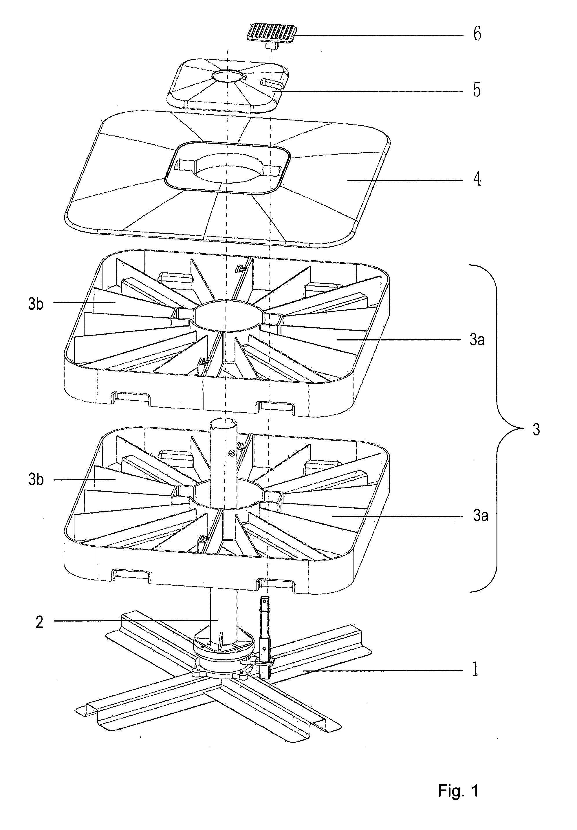
[0041]FIG. 1 shows an exploded view of the exemplary embodiment of the pole support according to the invention. Because FIG. 2 to FIG. 11 show the same pole support at different assembly stages and in different views, the description refers to FIG. 1. Further details will be discussed later, based on select figures.

[0042]The main element of the pole support is the pole base 1, connected to a pole holder 2 for an upright pole (not shown). To stabilize the pole base 1, a weight 3 is placed on it, consisting of half-shell or almost kidney-shaped elements 3a and 3b which are open to above and divided into segments. An upper element 3a is placed on a lower element 3a and an upper element 3b is placed on a lower element 3b. A cover plate 4, the opening of which is in turn covered by a cover closure 5, is used to cover the upper elements 3a and 3b. In addition, the foot control 6 is illustrated which is arranged above the cover closure 5.

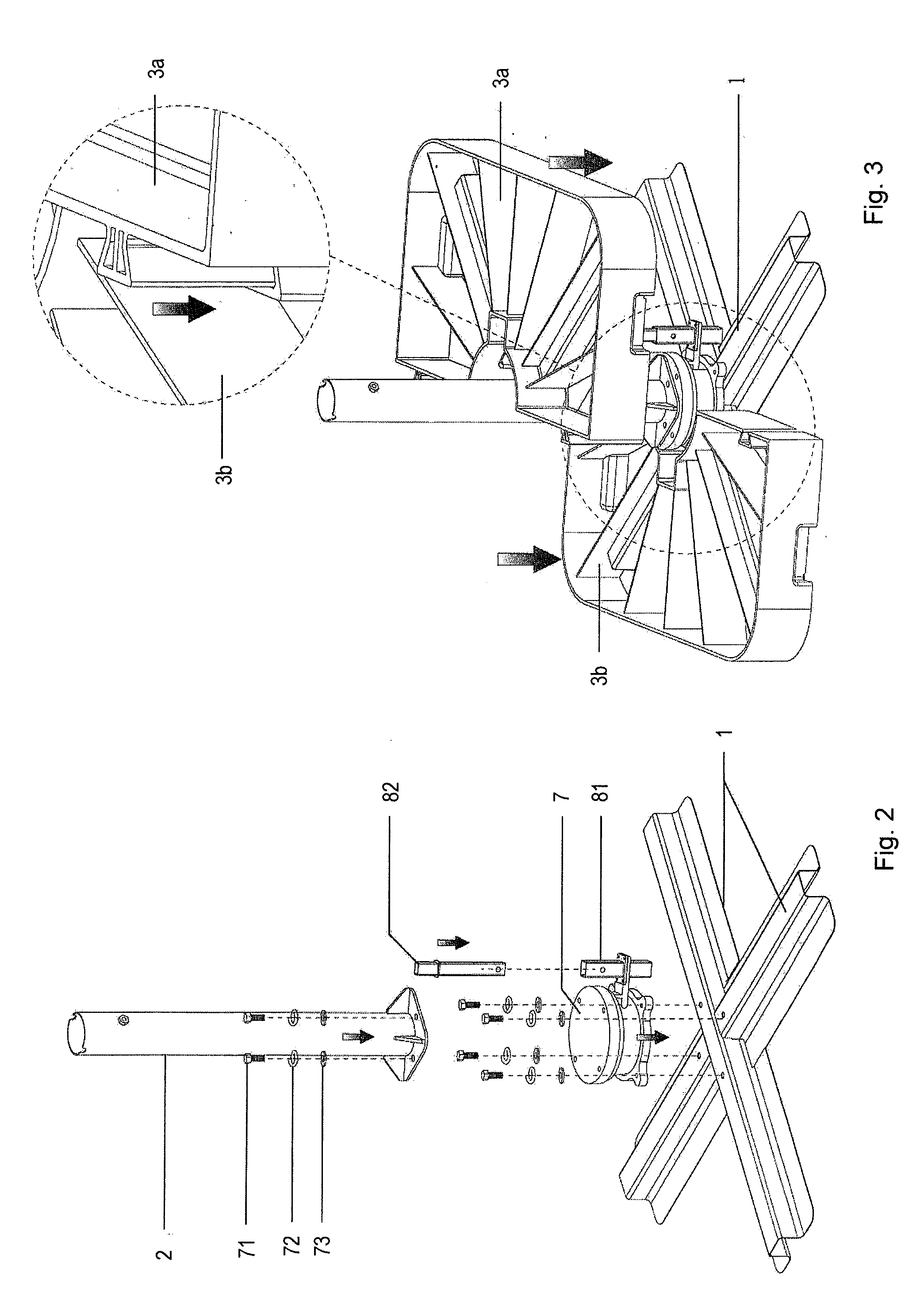
[0043]The pole base 1 is designed as a crossed stand...


PUM


Abstract

A pole support for an upright pole, preferably for use with an upright pole of a sunshade, umbrella or other similar product, that comprises a pole base, a pole holder connected to said pole base for the upright pole, and a weight, wherein the weight is configured to act upon the pole base to stabilize the pole base, and wherein the weight is configured to be detached from the pole base.

Description

CROSS-REFERENCE TO RELATED APPLICATIONS[0001]The present application claims priority from German Patent Application No. 10 2007012 223.5, filed Mar. 12, 2007. The disclosure of the referenced application is incorporated herein by reference.FIELD OF THE INVENTION[0002]The invention relates to a pole support for an upright pole, preferably for the upright pole of a sunshade, umbrella or similar product, with a pole base and connected or integrated pole holder for the upright pole.BACKGROUND OF THE INVENTION[0003]Sunshades, umbrellas and similar other garden or leisure products which include an upright pole for anchoring on the floor have been available on the market in various designs for some time. Upright umbrellas on terraces, balconies, in gardens and other outside facilities provide valuable services as reliable shades or protection from the rain. In order to provide shade or protection from the rain to an area as large as possible, the size of the umbrella canopies became gradua...

Claims


Application Information

Patent Timeline
IPC IPC(8): E04H12/22
CPCE04H12/2246A45B2200/109
Inventor DEFU, LIUKAI, LIU
Owner ZHEJIANG YOTRIO GRP CO LTD
Why Eureka
Try Eureka