Internal Combustion Engine
- Summary
- Abstract
- Description
- Claims
- Application Information
AI Technical Summary
Benefits of technology
Problems solved by technology
Method used
Image
Examples
Embodiment Construction
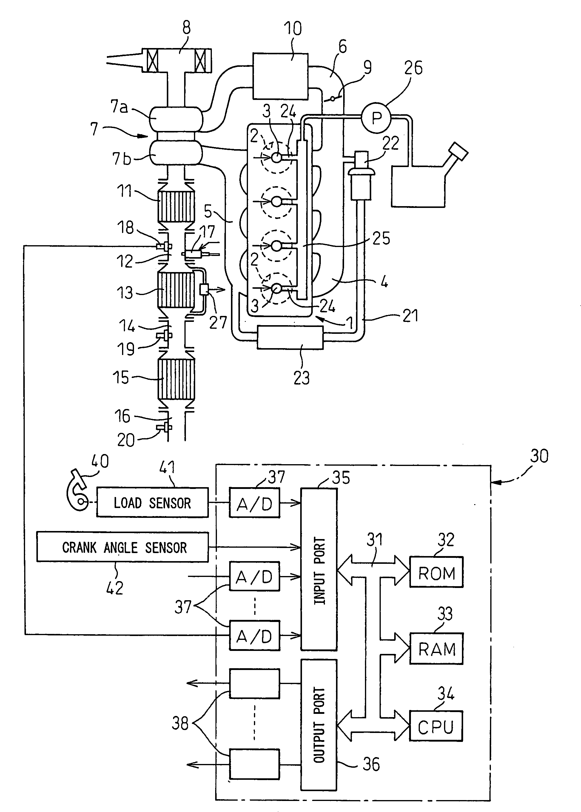
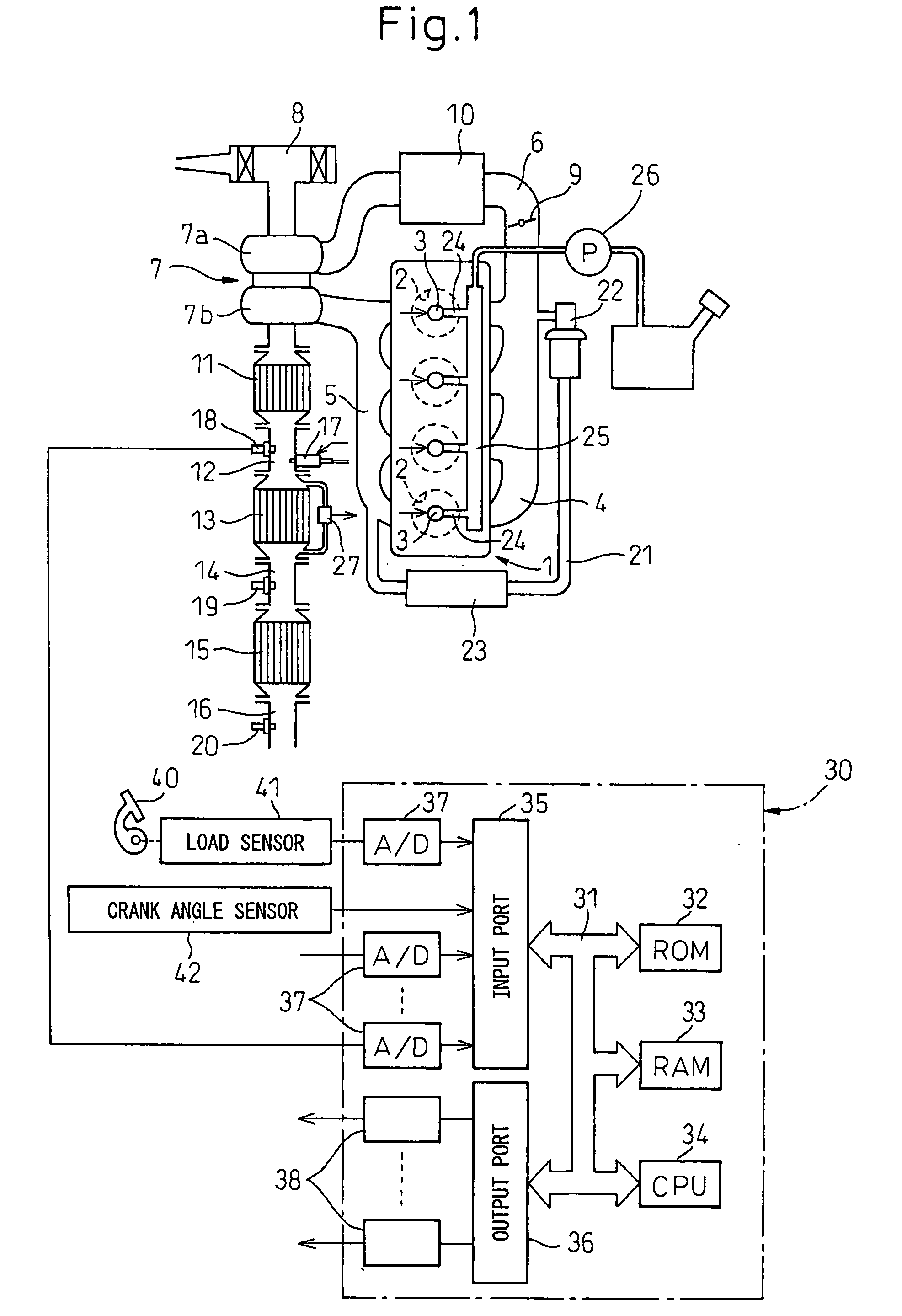
[0017]FIG. 1 shows an overview of a combustion ignition type internal combustion engine.
[0018]Referring to FIG. 1, 1 indicates an engine body, 2 a combustion chamber of a cylinder, 3 an electronic control type fuel injector for injecting fuel into a combustion chamber 2, 4 an intake manifold, and 5 an exhaust manifold. The intake manifold 4 is connected via an intake duct 6 to an outlet of a compressor 7a of an exhaust turbocharger 7, while an inlet of the compressor 7a is connected to an air cleaner 8. The intake duct 6 has a throttle valve 9 driven by a step motor arranged inside it. Further, around the intake duct 6, a cooling system 10 for cooling the intake air flowing through the inside of the intake duct 6 is arranged. In the embodiment shown in FIG. 1, the engine cooling water is led into the cooling system 10 where the engine cooling water cools the intake air.
[0019]On the other hand, the exhaust manifold 5 is connected to an inlet of the exhaust turbine 7b of the exhaust t...
PUM
 Abstract
Description
Claims
Application Information
 - R&D
- Intellectual Property
- Life Sciences
- Materials
- Tech Scout
- Unparalleled Data Quality
- Higher Quality Content
- 60% Fewer Hallucinations
Browse by: Latest US Patents, China's latest patents, Technical Efficacy Thesaurus, Application Domain, Technology Topic, Popular Technical Reports.
© 2025 PatSnap. All rights reserved.Legal|Privacy policy|Modern Slavery Act Transparency Statement|Sitemap|About US| Contact US: help@patsnap.com


