
Methods and apparatus for reducing the effects of DAC images in radio frequency transceivers

a radio frequency transceiver and image reduction technology, applied in the field of digital communication systems, can solve the problems of difficult to meet the noise requirements specified by standards, difficult to design analog filters having such characteristics, and difficult to attract attention, so as to reduce the effect of digital-to-analog converter (dac) images, reduce the desensitization of the receiver portion, and increase the dac

Inactive Publication Date: 2008-09-11
PANASONIC CORP
View PDF12 Cites 28 Cited by
  • Summary
  • Abstract
  • Description
  • Claims
  • Application Information

AI Technical Summary

Benefits of technology

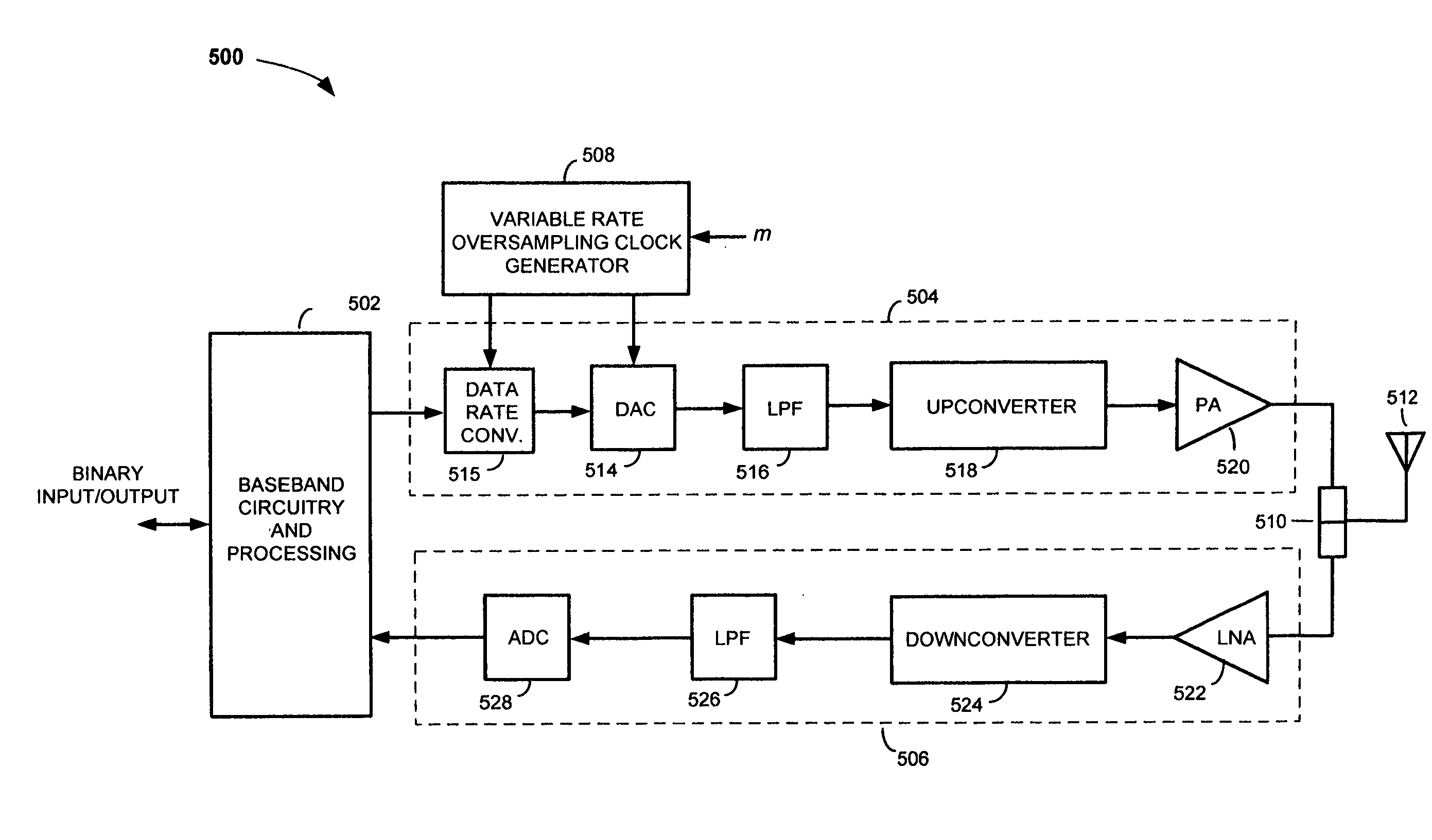
[0013]Methods and apparatus for reducing the effects of digital-to-analog converter (DAC) images and transmission spurious effects in a receive frequency band of a radio frequency (RF) transceiver are disclosed. An exemplary transceiver apparatus includes a transmitter portion having a digital signal processing block that accomplishes data rate conversion and a DAC; a receiver portion configured to receive RF signals in a receive frequency band; and a variable rate clock generator. The variable rate clock generator and digital signal processing block are used to provide oversampled clock and data for the DAC. The rate of the oversampled clock and data is adjustable and is selected so that an upconverted version of a DAC image created by the DAC is steered away from frequencies within the receive frequency band. In multi-mode or multi-band applications the rate of the oversampled clock and data can be adjusted so that DAC images do not fall within other receive frequency bands of interest. Among other benefits, shifting DAC images away from receive frequency bands of interest reduces desensitization of the receiver portion of the transceiver, and helps to ensure that specified receive noise requirements are satisfied. FIG. 6 shows the new output PSD shifted DAC image 606 that was accomplished by increasing the DAC clock frequency and increasing digital rate conversion by a factor of “m”. This new output PSD provides greater signal attenuation in the band of interest 604.
[0014]In addition to, or as an alternative to the DAC image shifting apparatus and methods, a digital low-pass filter that operates as a notch filter (i.e. a notch-effect low-pass filter (NELPF)) is used in the transceiver. According this aspect of the invention the notch frequency of the NELPF may be controlled by the same variable rate oversampling clock that is used by the DAC in the transmitter portion of the transceiver. The variable rate clocking provided by the variable rate clock generator thereby allows the notch frequency to be placed at frequency where a desired receive frequency band is located. In this manner undesirable transmission energy can be significantly reduced in bands of interest.

Problems solved by technology

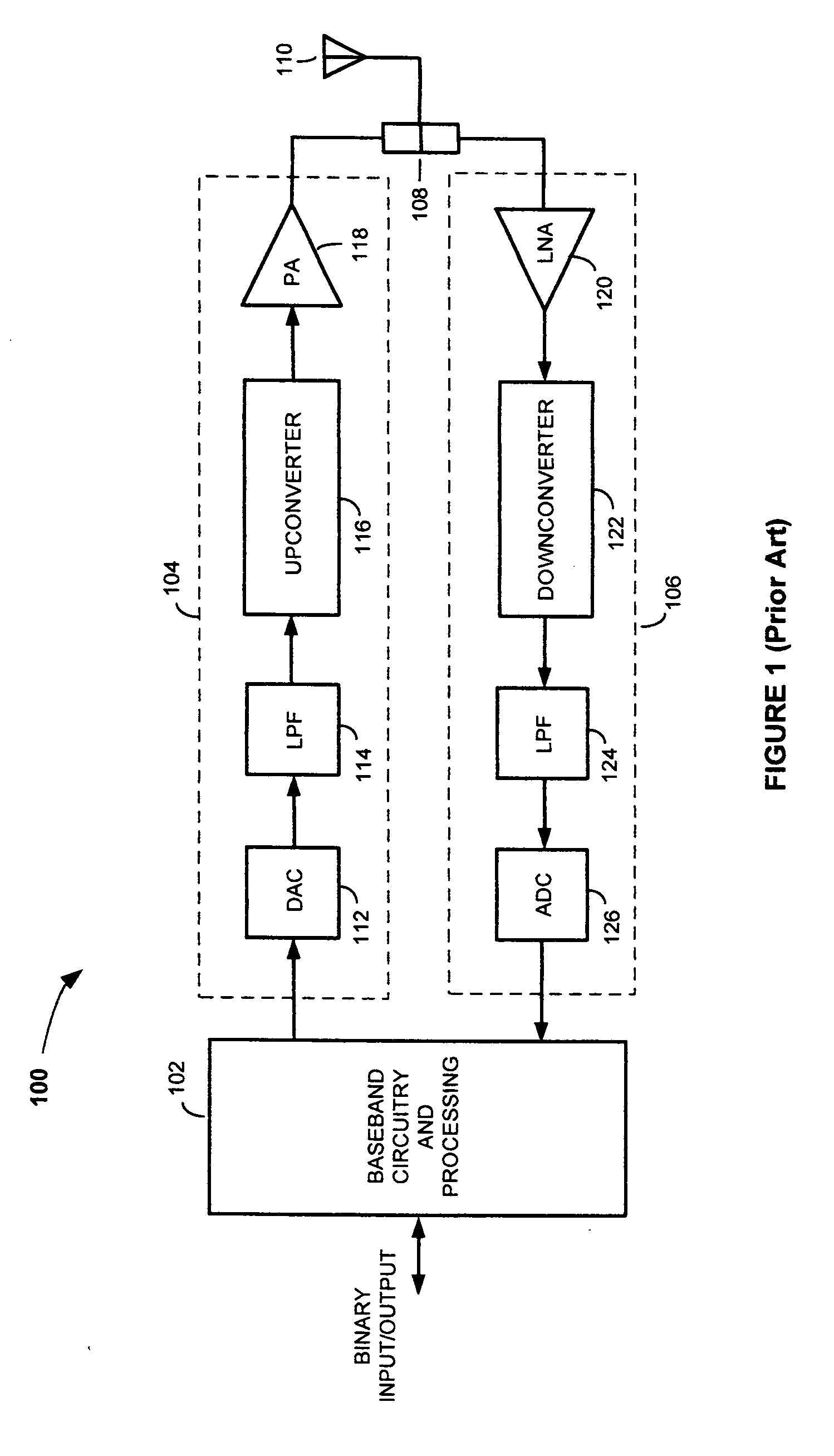
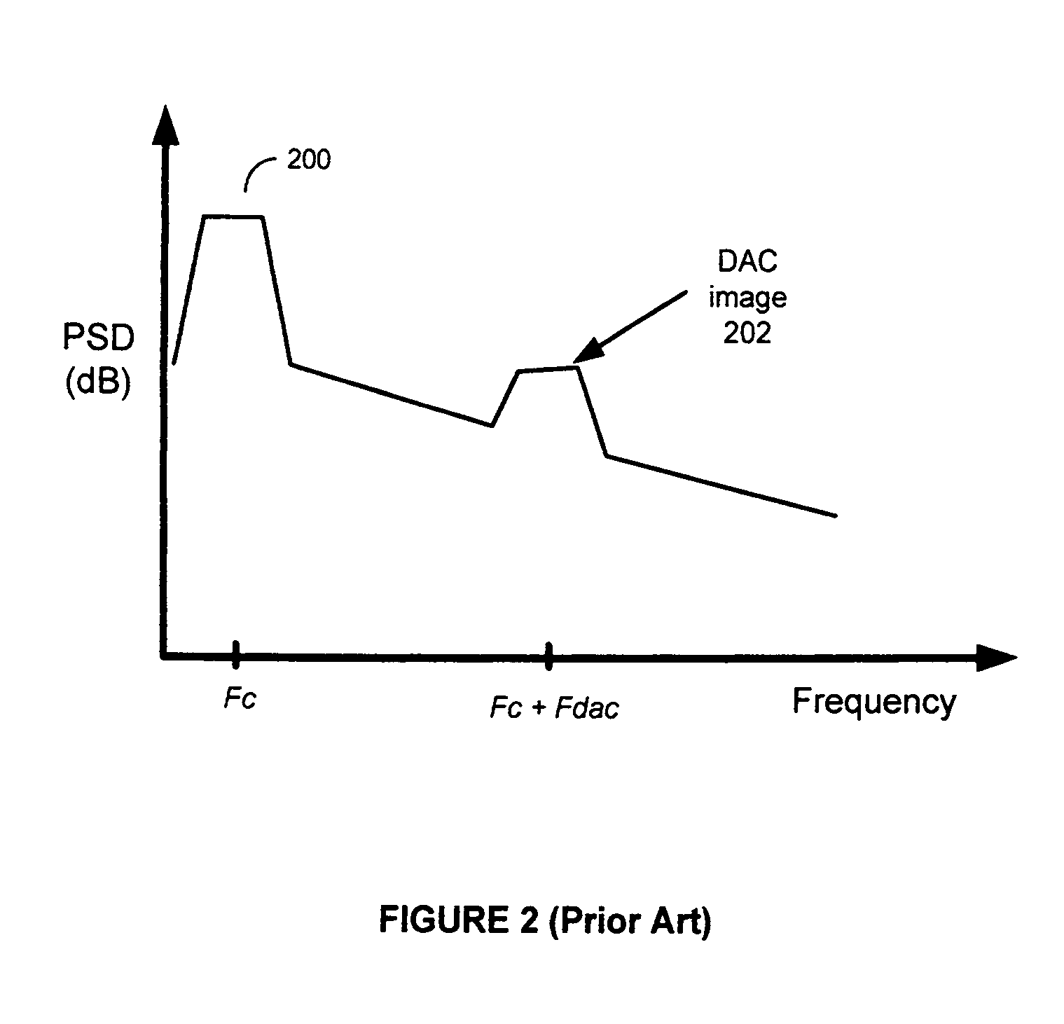
They are undesirable, however, since they contribute to noise, can desensitize the receiver portion 106 of the transceiver 100, and can make it difficult to comply with noise requirements specified by standards.
This approach is not very attractive, however, since the LPF must be a high-quality analog filter with a sharp cut-off frequency.
Because an analog filter having such characteristics is difficult to design, and would be costly to manufacture, other approaches to removing DAC images have been sought.
While oversampling can be used to steer DAC images away from a receive band in some applications, in other applications such as, for example, multi-band or multi-mode applications, it cannot.
Unfortunately, −150 dBm / Hz is much higher than the maximum allowable noise power density specified by the UTRA / FDD standard.

Method used


Image

  • Methods and apparatus for reducing the effects of DAC images in radio frequency transceivers
  • Methods and apparatus for reducing the effects of DAC images in radio frequency transceivers
  • Methods and apparatus for reducing the effects of DAC images in radio frequency transceivers

Examples


Embodiment Construction

[0030]Those of ordinary skill in the art will realize that the following detailed description of the present invention is illustrative only and is not intended to be in any way limiting. Other embodiments of the present invention will readily suggest themselves to such skilled persons having the benefit of this disclosure. Reference will now be made in detail to implementations of the present invention as illustrated in the accompanying drawings. The same reference indicators will be used throughout the drawings and the following detailed description to refer to the same or like parts.

[0031]FIG. 5 shows an RF transceiver 500 according to an embodiment of the present invention. The transceiver 500 comprises baseband circuit and processing block 502, a transmitter portion 504, a receiver portion 506, a variable rate (i.e., adjustable) oversampling clock generator 508, a duplexer 510 and an antenna 512. The transmitter portion 504 of the transceiver 500 includes a data rate conversion ...


PUM


Abstract

Methods and apparatus for reducing the effects of digital-to-analog converter (DAC) images and transmission spurious effects in a receive frequency band of a radio frequency (RF) transceiver. A transceiver apparatus includes a transmitter portion having a DAC, a receiver portion configured to receive RF signals in a receive frequency band, and a variable rate clock generator. The variable rate clock generator is used to provide an oversampling clock for the DAC. The rate of the oversampling clock is adjustable and is selected so that an upconverted version of a DAC image created by the DAC is steered away from frequencies within the receive frequency band. A notch-effect low-pass filter (NELPF) may also, or alternatively, be used in the transceiver to reduce transmission spurious effects in the receive frequency band.

Description

FIELD OF THE INVENTION[0001]The present invention relates generally to digital communications systems. More specifically, the present invention relates to reducing noise in multi-mode and multi-band transceivers.BACKGROUND OF THE INVENTION[0002]Wireless communication technologies have developed rapidly over the years, particularly since first generation (1G) mobile communications systems were introduced for public use in the early 1980s. In recent years, analog 1G systems have been superseded by second and third generation (2G and 3G) digital communications systems. Digital systems provide a number of benefits over analog systems including improved spectral efficiency, higher signal quality, enhanced security features (e.g., by way of digital encryption) and the ability to be manufactured in the form of Very Large Scale Integrated (VLSI) circuits.[0003]The basic building blocks of any wireless communication device are the device's transmitter and receiver. In many applications the t...

Claims


Application Information

Patent Timeline
Patent Type & Authority Applications(United States)
IPC IPC(8): H04L5/16
CPCH04B1/0475H04B1/525H03M3/376H03M3/344H03M3/50
Inventor LIANG, PAUL CHENG-POSTRANDBERG, RICHARD H.
Owner PANASONIC CORP
Learn More