
Micro-droplet ejection apparatus having nozzle arrays without individual chambers and ejection method of droplets thereof

Active Publication Date: 2008-09-11
NATIONAL TSING HUA UNIVERSITY
View PDF16 Cites 0 Cited by
  • Summary
  • Abstract
  • Description
  • Claims
  • Application Information

AI Technical Summary

Benefits of technology

[0010]The present invention provides a micro-droplet ejection apparatus with high frequency and high resolution, which has nozzles arranged in an array, and adopts a design with no individual fluid cavities under the nozzles, thereby increasing nozzle density in a unit area.
[0011]The present invention provides a micro-droplet ejection apparatus that is easy to design and manufacture, which can be finished with a micro-electromechanical process or a common semiconductor process.
[0012]The present invention provides an ejection method for droplets, forming a bubble wrapped in the liquid on at least one side of a micro-nozzle orifice, thereby controlling the direction of expansion of a bubble in another liquid generated under the micro-nozzle orifice, so as to increase the frequency of droplet ejection and to prevent the occurrence of satellite droplets.

Problems solved by technology

The disadvantages of the thermally driven bubble system (also referred to as the bubble injection system) are the problems of cross talk and satellite droplets.
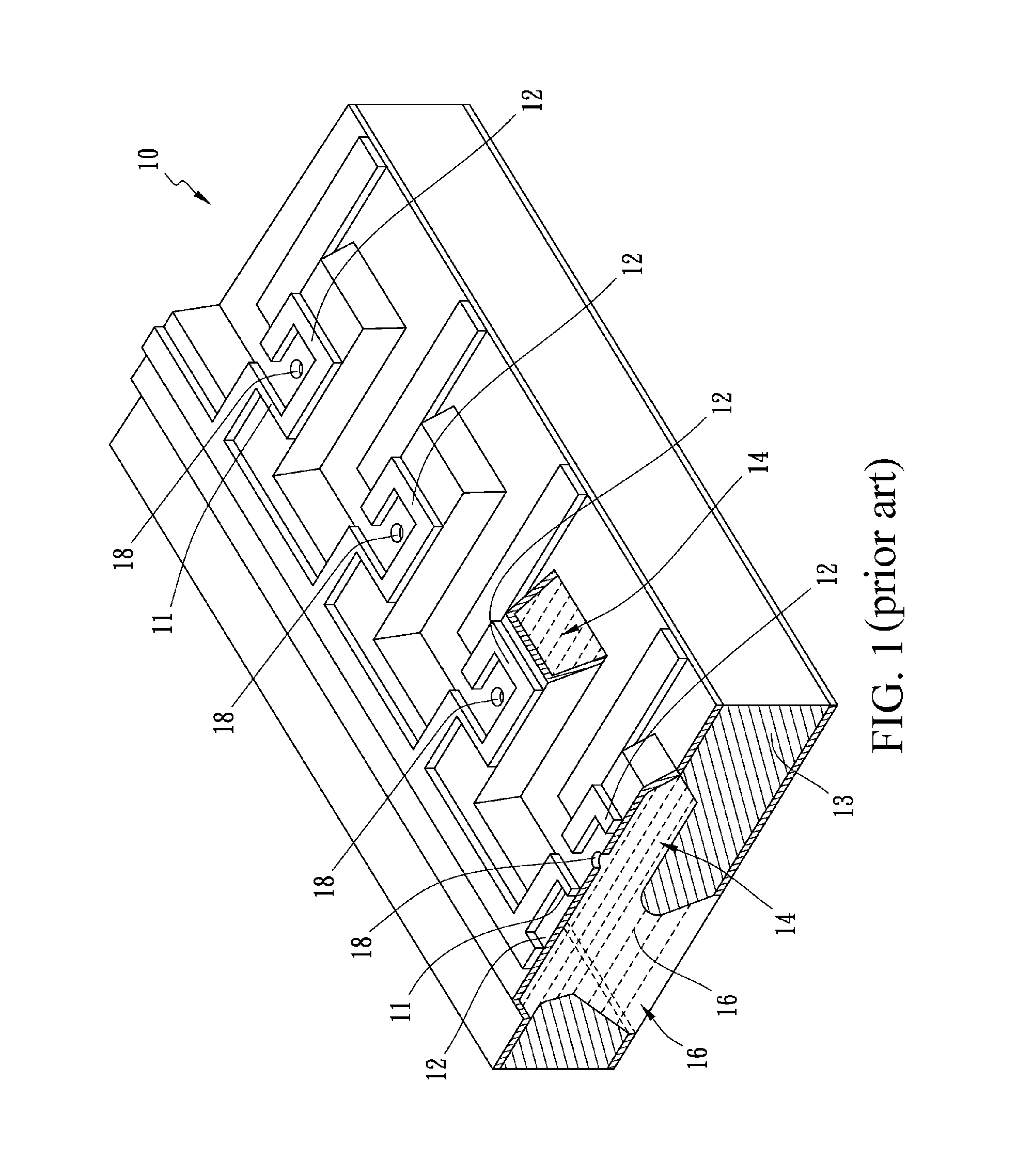
However, the fluid cavities corresponding to the micro-nozzle orifices are isolated by spacers, resulting in flow resistance when the liquid refills the liquid cavities.
If the length of the spacers between the liquid cavities is reduced, the problems of the cross talk and the over refilling between the neighboring liquid cavities may occur.
If the distance between the fluid cavities 14 is inappropriately reduced, it is liable to induce the cross talk.

Method used


Image

  • Micro-droplet ejection apparatus having nozzle arrays without individual chambers and ejection method of droplets thereof
  • Micro-droplet ejection apparatus having nozzle arrays without individual chambers and ejection method of droplets thereof
  • Micro-droplet ejection apparatus having nozzle arrays without individual chambers and ejection method of droplets thereof

Examples


Embodiment Construction

[0029]The present invention is explained with the accompanying drawings as follows, so as to clearly disclose the technical features of the present invention.

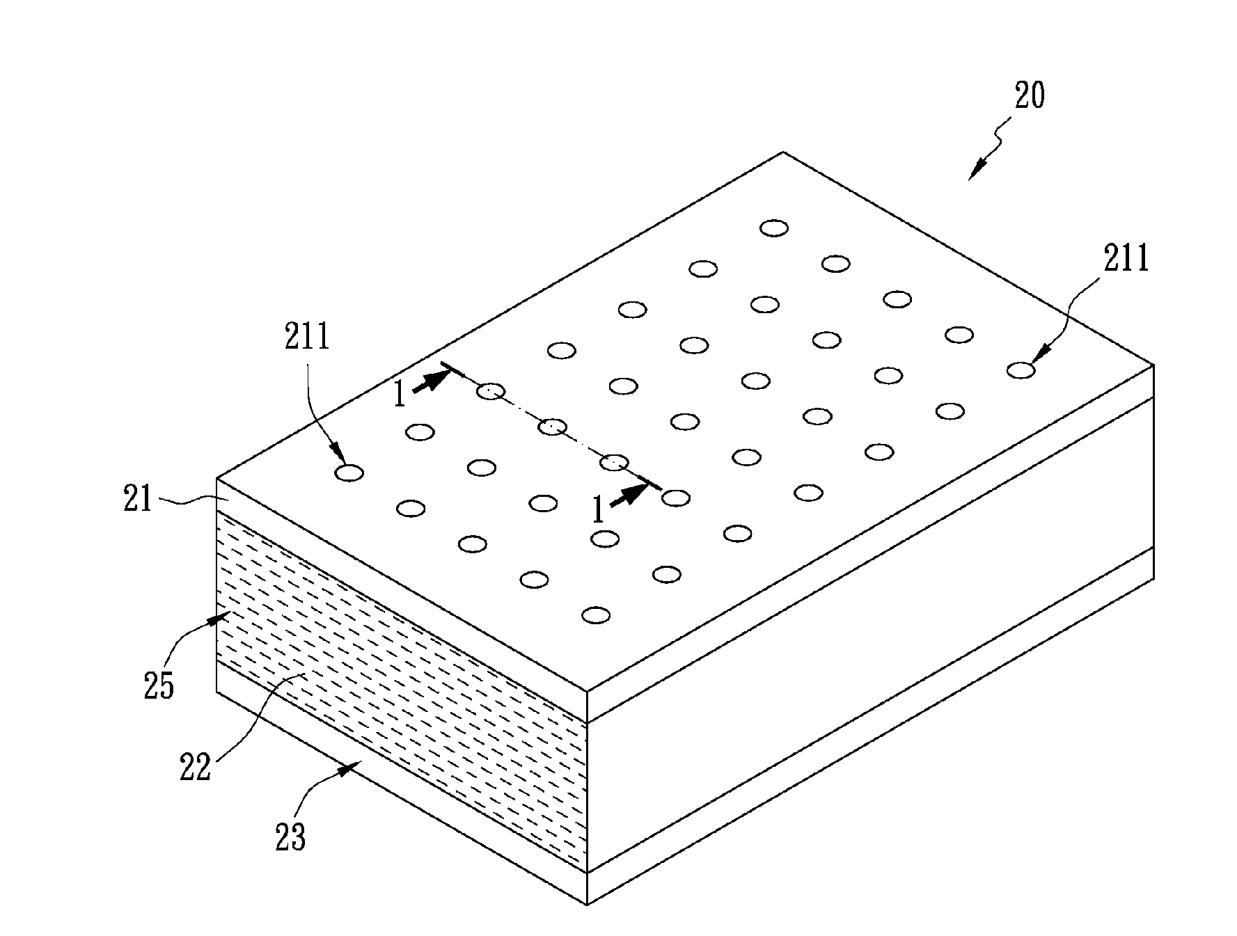
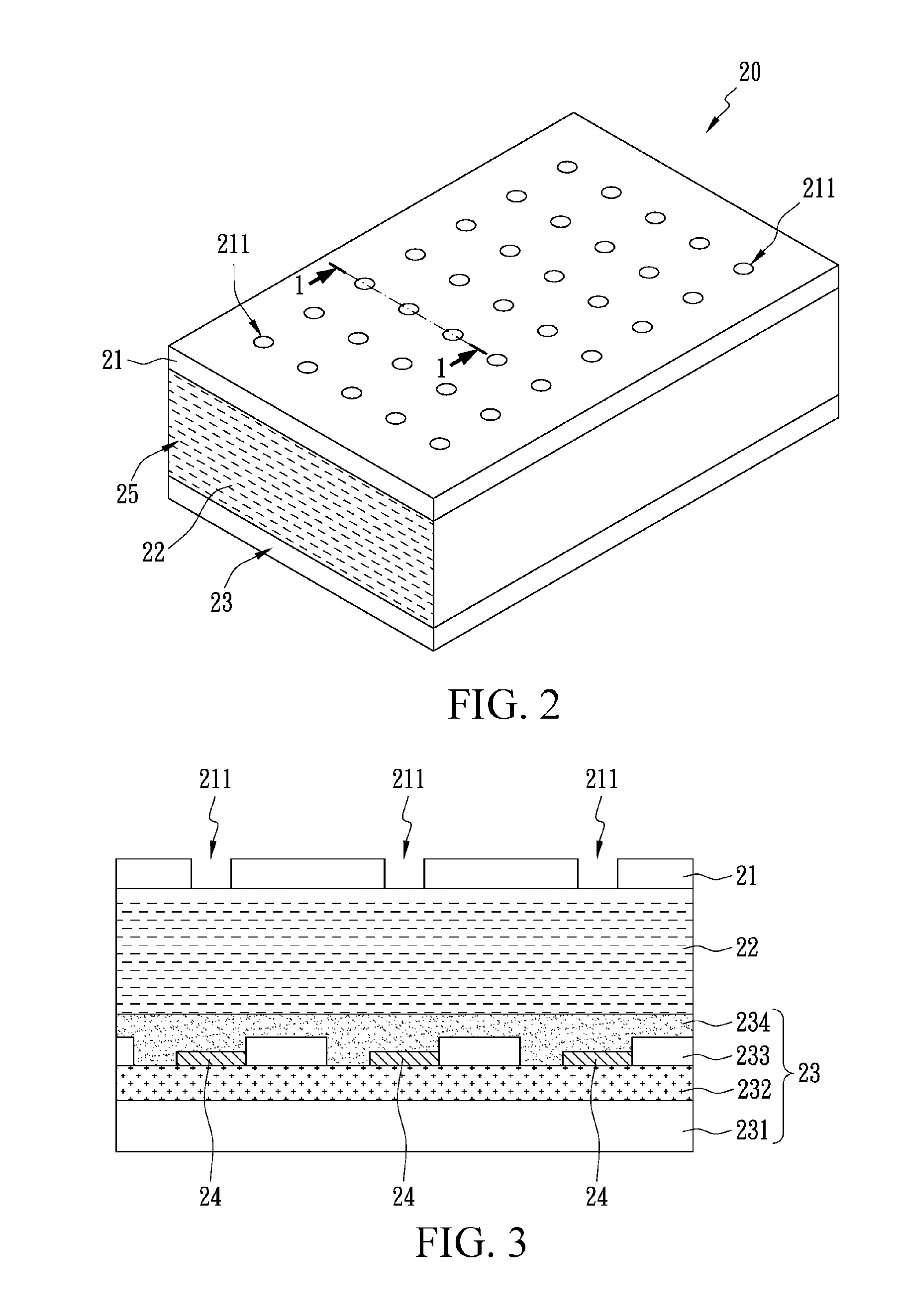
[0030]FIG. 2 shows a nozzle array 20 of a micro-droplet ejection apparatus. However, the micro-droplet ejection apparatus can include a plurality of nozzle arrays 20. The nozzle array 20 includes a substrate 23, a droplet ejection layer 21, and a plurality of bubble generators 24. A liquid storage space 25 filled with ink 22 or liquid is formed between the substrate 23 and the droplet ejection layer 21. The liquid storage space 25 has no spacers connecting the substrate 23 and the droplet-ejecting layer 21. That is, the liquid storage space 25 does not have individual chambers similar to the fluid cavities 14 in FIG. 1. The droplet ejection layer 21 has a plurality of through holes 211 arranged in an array, and each through hole 211 is used as a nozzle for pushing out the ink 22.

[0031]FIG. 3 is a sectional view of FIG. 2 taken ...


PUM


Abstract

A micro-droplet ejection apparatus includes a substrate, a droplet-ejecting layer, and a plurality of bubble generators. A liquid storage space is formed between the substrate and the droplet-ejecting layer. The liquid storage space has no spacer connecting the substrate and the droplet-ejecting layer. That is, the liquid storage space has no individual chambers. The droplet-ejecting layer has a plurality of through holes arranged in an array, and each through hole is used as a nozzle for pushing out ink. The plurality of bubble generators is disposed above the substrate, and corresponds to and is disposed under the through holes. The bubble generators on two sides of a designated bubble generator generate at least one limit bubble, limiting the growth of a main bubble generated by the designated bubble generator.

Description

BACKGROUND OF THE INVENTION[0001]1. Field of the Invention[0002]The present invention relates to a micro-droplet ejection apparatus having nozzle arrays without individual chambers and an ejection method of droplets thereof. More particularly, the present invention relates to a micro-droplet generating apparatus with high nozzle density and a method for ejecting micro-droplets.[0003]2. Description of the Related Art[0004]Micro-droplet ejection apparatuses are widely applied in inkjet printheads of inkjet printers. In addition, the micro-droplet ejectors can also be applied in other technical fields, for example, fuel injection systems, cell classification, pharmaceutical release systems, reagent distribution on biochips, direct jet printing photolithography, and micro-injection propelling systems. The common point of all of the above-mentioned applications is that a reliable micro-droplet ejection apparatus with low cost, high frequency, and high resolution is required.[0005]Recentl...

Claims


Application Information

Patent Timeline
IPC IPC(8): B41J2/05B41J2/17
CPCB41J2/1404B41J2002/14387B41J2002/1437B41J2/14056
Inventor TSENG, FAN GANGYANG, I DA
Owner NATIONAL TSING HUA UNIVERSITY
Learn More