
Inkjet printhead with deep reverse etch in integrated circuit wafer

Inactive Publication Date: 2005-05-12
ZAMTEC +1
View PDF10 Cites 20 Cited by
  • Summary
  • Abstract
  • Description
  • Claims
  • Application Information

AI Technical Summary

Benefits of technology

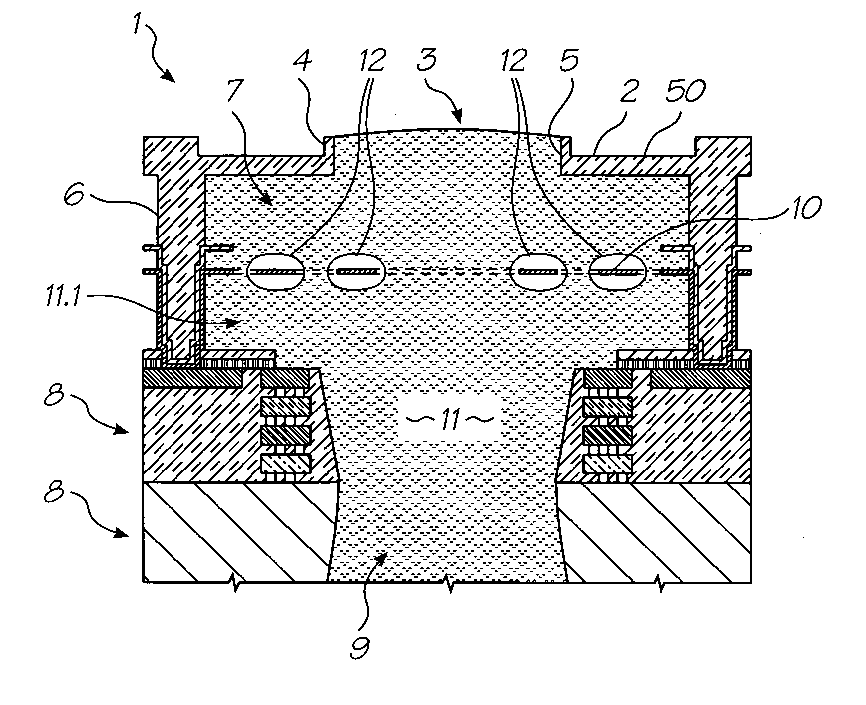
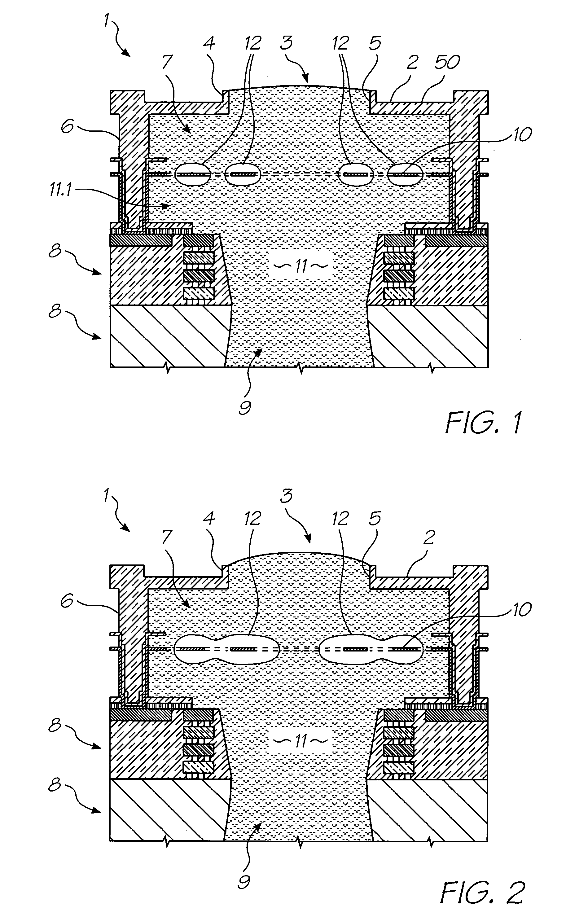
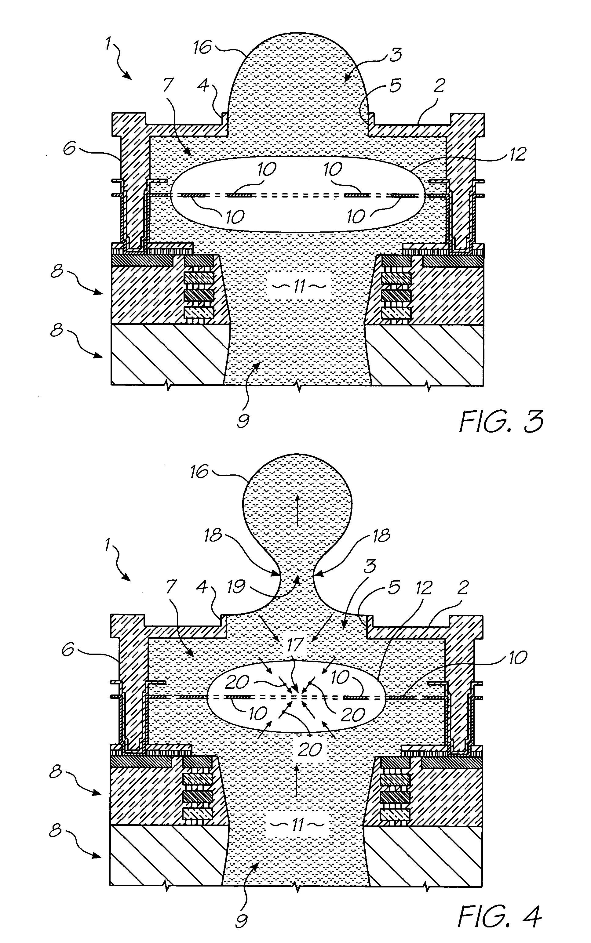
[0014] Etching the wafer from both sides eliminates ink feed conduits on the ejections side of the wafer. This allows nozzle density to increase. By making the reverse etch deep (greater than 100 microns), the viscous drag will provide enough resistance to substantially prevent reverse ink flow from the bubble in the chamber.

Problems solved by technology

As the vapor cools, it recondenses, resulting in bubble collapse.

Method used


Image

  • Inkjet printhead with deep reverse etch in integrated circuit wafer
  • Inkjet printhead with deep reverse etch in integrated circuit wafer
  • Inkjet printhead with deep reverse etch in integrated circuit wafer

Examples


Embodiment Construction

[0080] In the description than follows, corresponding reference numerals, or corresponding prefixes of reference numerals (i.e. the parts of the reference numerals appearing before a point mark), which are used in different figures, relate to corresponding parts. Where there are corresponding prefixes and differing suffixes to the reference numerals, these indicate different specific embodiments of corresponding parts.

Overview of the Invention and General Discussion of Operation

[0081] With reference to FIGS. 1 to 4, the unit cell 1 of a printhead according to an embodiment of the invention comprises a nozzle plate 2 with nozzles 3 therein, the nozzles having nozzle rims 4, and apertures 5 extending through the nozzle plate. The nozzle plate 2 is plasma etched from a silicon nitride structure which is deposited, by way of chemical vapor deposition (CVD), over a sacrificial material which is subsequently etched.

[0082] The printhead also includes, with respect to each nozzle 3, sid...


PUM


Abstract

An inkjet printhead with nozzles (3), chambers (7) and heater elements (10) formed on an ejection side of a silicon wafer substrate (8) using lithographically masked etching and deposition techniques, and conduits (9) are etched into the reverse side of the silicon wafer (8) opposite the ejection side, the conduits (9) being configured for feeding bubble forming liquid (11) to the bubble forming chambers (7), wherein, the conduits (7) are etched to a depth greater than 100 microns from the reverse side of the wafer (8). Etching the wafer from both sides eliminates ink feed conduits on the ejections side of the wafer. This allows nozzle density to increase. By making the reverse etch deep (greater than 100 microns), the viscous drag will provide enough resistance to substantially prevent reverse ink flow from the bubble in the chamber.

Description

[0002] This is a Continuation of U.S. Ser. No. 10 / 773,190 filed Feb. 9, 2004 which is Continuation-in-Part of Ser. No. 10 / 302,274 filed Nov. 23, 2002 all of which are herein incorporated by reference.FIELD OF THE INVENTION [0003] The present invention relates to a thermal ink jet printhead, to a printer system incorporating such a printhead, and to a method of ejecting a liquid drop (such as an ink drop) using such a printhead. BACKGROUND TO THE INVENTION [0004] The present invention involves the ejection of ink drops by way of forming gas or vapor bubbles in a bubble forming liquid. This principle is generally described in U.S. Pat. No. 3,747,120 (Stemme). [0005] There are various known types of thermal ink jet (bubblejet) printhead devices. Two typical devices of this type, one made by Hewlett Packard and the other by Canon, have ink ejection nozzles and chambers for storing ink adjacent the nozzles. Each chamber is covered by a so-called nozzle plate, which is a separately fabric...

Claims


Application Information

Patent Timeline
IPC IPC(8): B41J2/14B41J2/16
CPCB41J2/04518B41J2/14427B41J2/04555B41J2/0457B41J2/0458B41J2/04588B41J2/1404B41J2/14072B41J2/1408B41J2/1412B41J2/155B41J2/1601B41J2/1603B41J2/1623B41J2/1626B41J2/1628B41J2/1631B41J2/1635B41J2/1639B41J2/1642B41J2/1646B41J2002/14475B41J2002/14491B41J2202/11B41J2202/19B41J2202/20B41J2202/21B41J2/0452B41J2/05B82Y99/00
Inventor SILVERBROOK, KIA
Owner ZAMTEC
Learn More