
Scale

a scale and scale technology, applied in the field of scales, can solve the problems of affecting measurement accuracy, affecting the /rear/left/right, and preventing further improvement of measurement accuracy, so as to reduce the size and prevent degradation of measurement accuracy

Inactive Publication Date: 2008-09-11
OMRON HEALTHCARE CO LTD
View PDF6 Cites 5 Cited by
  • Summary
  • Abstract
  • Description
  • Claims
  • Application Information

AI Technical Summary

Benefits of technology

[0012]Therefore, an object of the present invention is to provide a scale allowing further reduction in size while preventing degradation of measurement accuracy as much as possible.
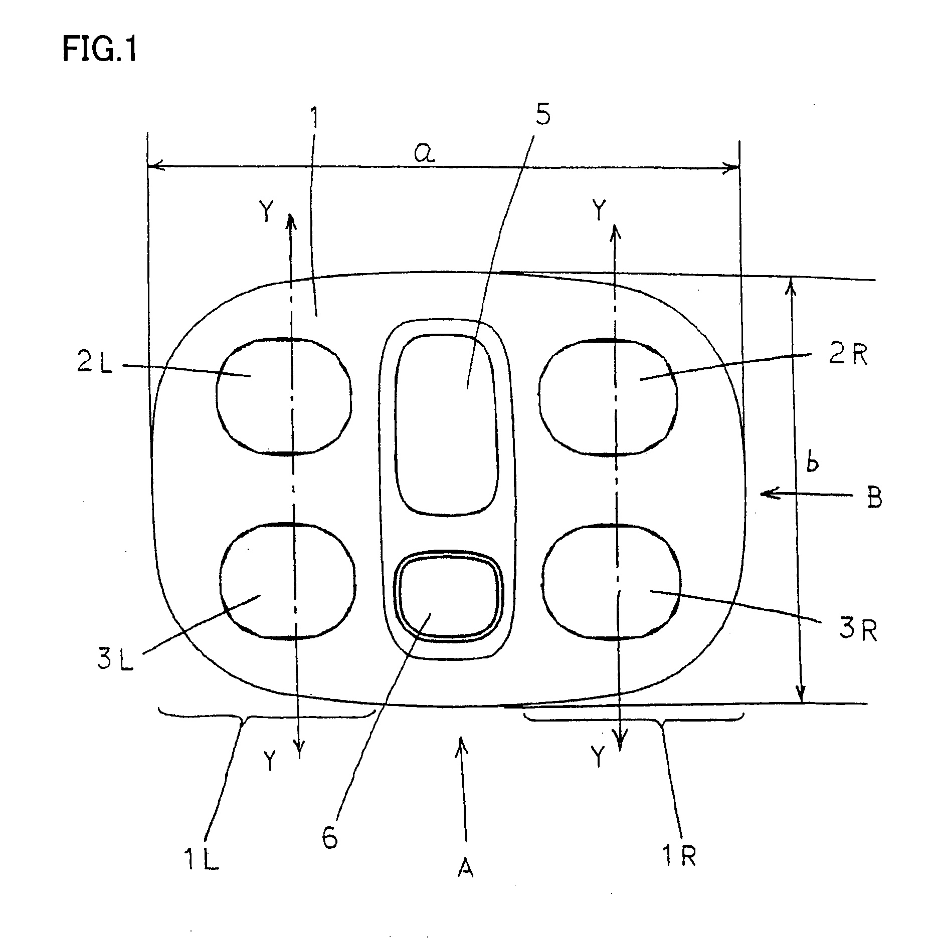
[0014]Focusing on the tendency that feet-receiving positions deviate in the front / rear direction rather than left / right direction when the user stands on the platform with his / her left and right feet positioned on the feet-receiving regions, in the scale, the load cells are arranged such that longitudinal direction of the load cells are aligned with the aforementioned orthogonal direction (left / right direction), so that error in measurement caused by the positional deviation in the front / rear direction can more effectively be compensated for. Thus, coupled with the tendency described above, further improvement of measurement accuracy can be attained.
[0015]Preferably, in the scale, the feet-receiving region has an angle of inclination different from that of a region outside the feet-receiving region (end portion). With the feet-receiving regions formed in this manner, coupled with the tendency that positional deviation in left / right direction is less likely than in the front / rear direction, deviation of feet-receiving positions in the left / right direction becomes much less likely. Specifically, when the user places his / her feet on the end portions of feet-receiving regions, he / she feels as if his / her feet slip or fall from the platform and, to avoid such situation, the user makes a conscious effort to surely place the feet on the feet-receiving regions. Thus, measurement accuracy can further be improved.
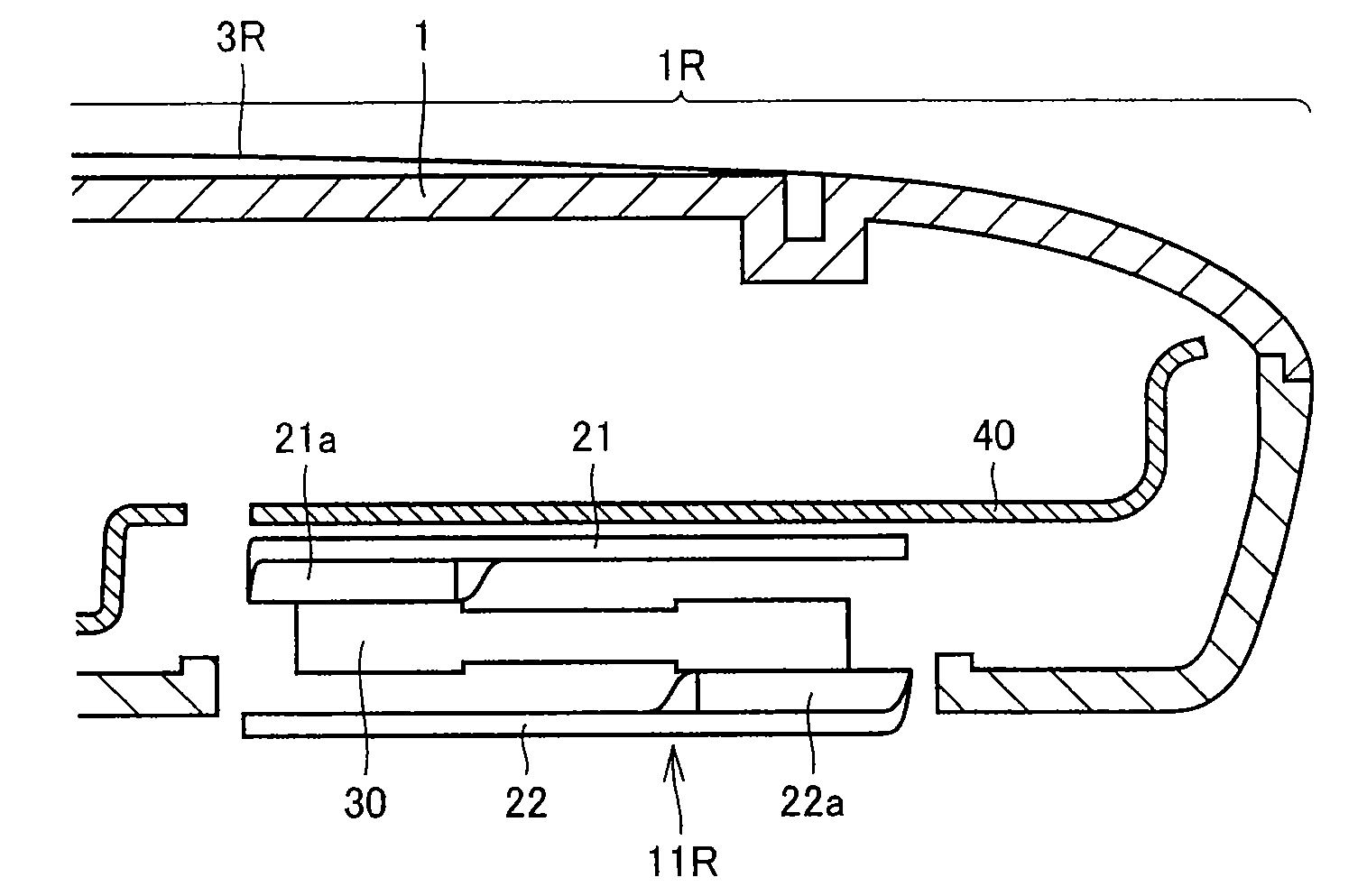
[0016]Further, in the scale described above, preferably, length in the direction connecting one's heel and toe (front / rear direction) of the platform is shorter than the longitudinal direction (left / right direction) of the elongate load cell of the platform (that is, the platform is horizontally long). In the scale of the present invention, load cell is arranged with its longitudinal direction aligned with the left / right direction and, therefore, even if the length of the platform in front / rear direction is short and the feet-receiving positions should deviate in the front / rear direction, the positional deviation in the front / rear direction hardly deflects the load cell and hence, the load cell is not influenced by the positional deviation in the front / rear direction. By this structure, it becomes possible to make the scale compact, as the length in the front / rear direction of the platform is shorter.
[0018]Here, desirably, the lateral width of the current electrode and the voltage electrode in the longitudinal direction of the elongate load cell corresponds to the lateral width of one's foot placed on the platform. By such an arrangement, when one places his / her feet on the feet-receiving regions of the platform, the foot surely contacts the current electrode and the voltage electrode, and measurement accuracy of body composition can be improved.

Problems solved by technology

This means that load point for a load cell in each load sensor varies at every measurement, which affects measurement accuracy.
In this regard, in the scales described in Japanese Utility Model Registration No. 3128216 and Japanese Patent Laying-Open No. 2003-149038, load cells are arranged along the diagonals of the platform to prevent degradation of measurement accuracy derived from variation of feet-receiving positions both in the front / rear and left / right directions, and therefore, both front / rear and left / right directions are susceptible to the influence of unfair values and, as a result, further improvement in measurement accuracy has been difficult.
Specifically, with the conventional arrangement of load cells, degradation of measurement accuracy caused by deviation in feet-receiving positions both in the front / rear and left / right directions cannot satisfactorily be prevented no matter whether the platform is vertically long, that is, large in front / rear direction or horizontally long, that is, large in left / right direction.
There is a demand for a scale allowing further reduction in size while preventing degradation in measurement accuracy as much as possible and, the conventional scales described above cannot meet such a demand.

Method used


Image

  • Scale
  • Scale
  • Scale

Examples


Embodiment Construction

[0039]In the following, an embodiment of the present invention will be described.

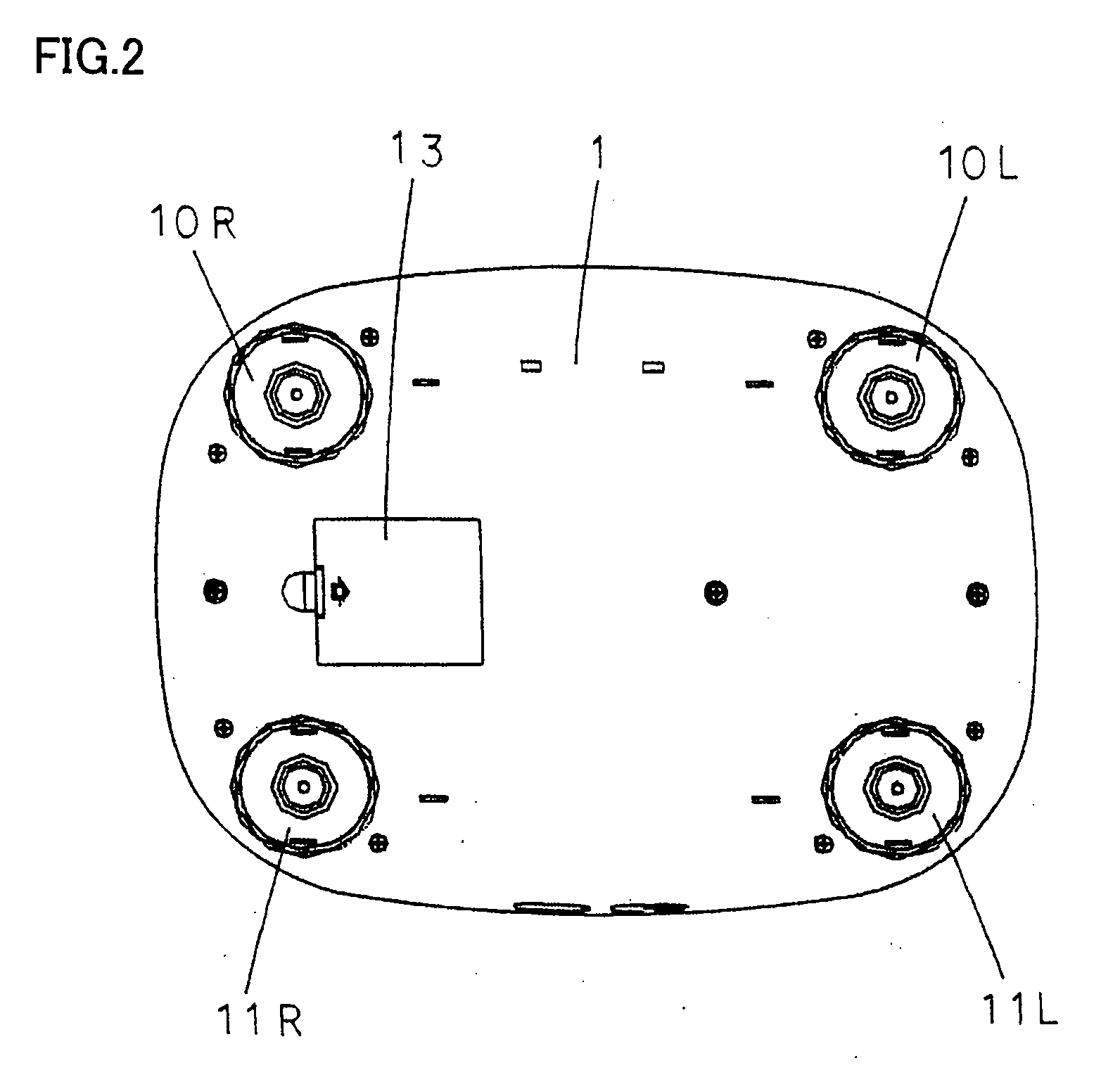
[0040]FIG. 1 is a plan view (top view), FIG. 2 is a bottom view, FIG. 3A is a front view from the direction of arrow A of FIG. 1 and FIG. 3B is a side view from the direction of arrow B shown in FIG. 1, of the scale in accordance with the embodiment.

[0041]The scale measures not only weight but also body composition (body fat ratio, body fat amount and body fat volume), and has a platform 1 as the main body. At the central portion of the platform 1 (central portion in the left / right direction), a display unit (liquid crystal display) 5 displaying the weight measurement or body composition and an operation unit 6 are provided. On opposite, left and right sides of the display unit and operation unit 6, left foot receiving region 1L and a right foot receiving region 1R are set. On foot-receiving region 1L, a current electrode 2L and a voltage electrode 3L for the left foot are provided, and on foot-receivin...


PUM


Abstract

A scale includes a platform, load sensors provided at four corners inside the platform, and a display unit. Each load sensor has an elongate load cell and a strain gauge. Each load cell is arranged such that its longitudinal direction is approximately orthogonal to the direction connecting heel and toe of the foot placed on the platform. The display unit is arranged at a central portion of the platform, and feet-receiving regions are set at opposite sides of the display unit. By such a structure, a scale allowing reduction in size while preventing degradation of measurement accuracy as much as possible can be realized.

Description

BACKGROUND OF THE INVENTION[0001]1. Field of the Invention[0002]The present invention relates to a scale provided with load sensors having load cells.[0003]2. Description of the Background Art[0004]A scale using load sensors having load cells generally includes a platform, load sensors provided at four corners inside the platform, and a display unit. Here, the display unit is arranged at a central portion on the front side of the platform, and feet-receiving regions are set on opposite, left and right sides of the display unit.[0005]For measuring weight using the scale as such, the user stands on the platform with his / her left and right feet placed on the feet-receiving regions. Feet size and shape vary widely and, therefore, the positions where the left and right feet are received naturally vary person to person, both in front / rear and left / right directions, and the positions of the left and right feet of even one user received on feet-receiving regions may vary both in front / rear ...

Claims


Application Information

Patent Timeline
Patent Type & Authority Applications(United States)
IPC IPC(8): G01G3/14
CPCG01G19/44
Inventor KODAKA, SHINYATANAKA, SHINYAIIDA, HIROSHI
Owner OMRON HEALTHCARE CO LTD
Learn More