
Vacuum carburization method and vacuum carburization apparatus

a vacuum carburization and vacuum carburization technology, applied in the direction of solid-state diffusion coating, coating, metallic material coating process, etc., can solve the problems of difficult to obtain a workpiece w having a predetermined property value, difficult to form fine crystal grains in the workpiece w, and temperature non-uniformity, etc., to shorten the process time, suppress the non-uniformity, the effect of shortening the process tim

Inactive Publication Date: 2008-09-11
IHI CORP
View PDF5 Cites 9 Cited by
  • Summary
  • Abstract
  • Description
  • Claims
  • Application Information

AI Technical Summary

Benefits of technology

The invention provides a vacuum carburization method and apparatus for carburizing a workpiece by heating it in a heating chamber, supplying carburizing gas to carburize it, stopping the supply of gas to diffuse carbon from the surface to the inside of the workpiece, and cooling it using a cooler. The method and apparatus allow for the production of fine crystal grains in the workpiece and the achievement of a predetermined temperature history. The method and apparatus can be performed in a state where the heating chamber is depressurized or filled with inert gas.

Problems solved by technology

However, when the vacuum carburization is performed, for example, at the treatment temperature X° C. of 1050° C., it is difficult to form fine crystal grains in the workpiece W due to bloating caused by the high temperature treatment.
Accordingly, it is difficult to obtain a workpiece W having a predetermined property value.
In addition, non-uniformity in temperature occurs between the surface and the inside of the workpiece and thus the crystal grains become non-uniform.

Method used


Image

  • Vacuum carburization method and vacuum carburization apparatus
  • Vacuum carburization method and vacuum carburization apparatus
  • Vacuum carburization method and vacuum carburization apparatus

Examples


Embodiment Construction

[0042]Hereinafter, an embodiment of a vacuum carburization apparatus and a vacuum carburization method according to the invention will be described with reference to the drawings. In the drawings, the scale of each of the members is appropriately modified for ease of viewing.

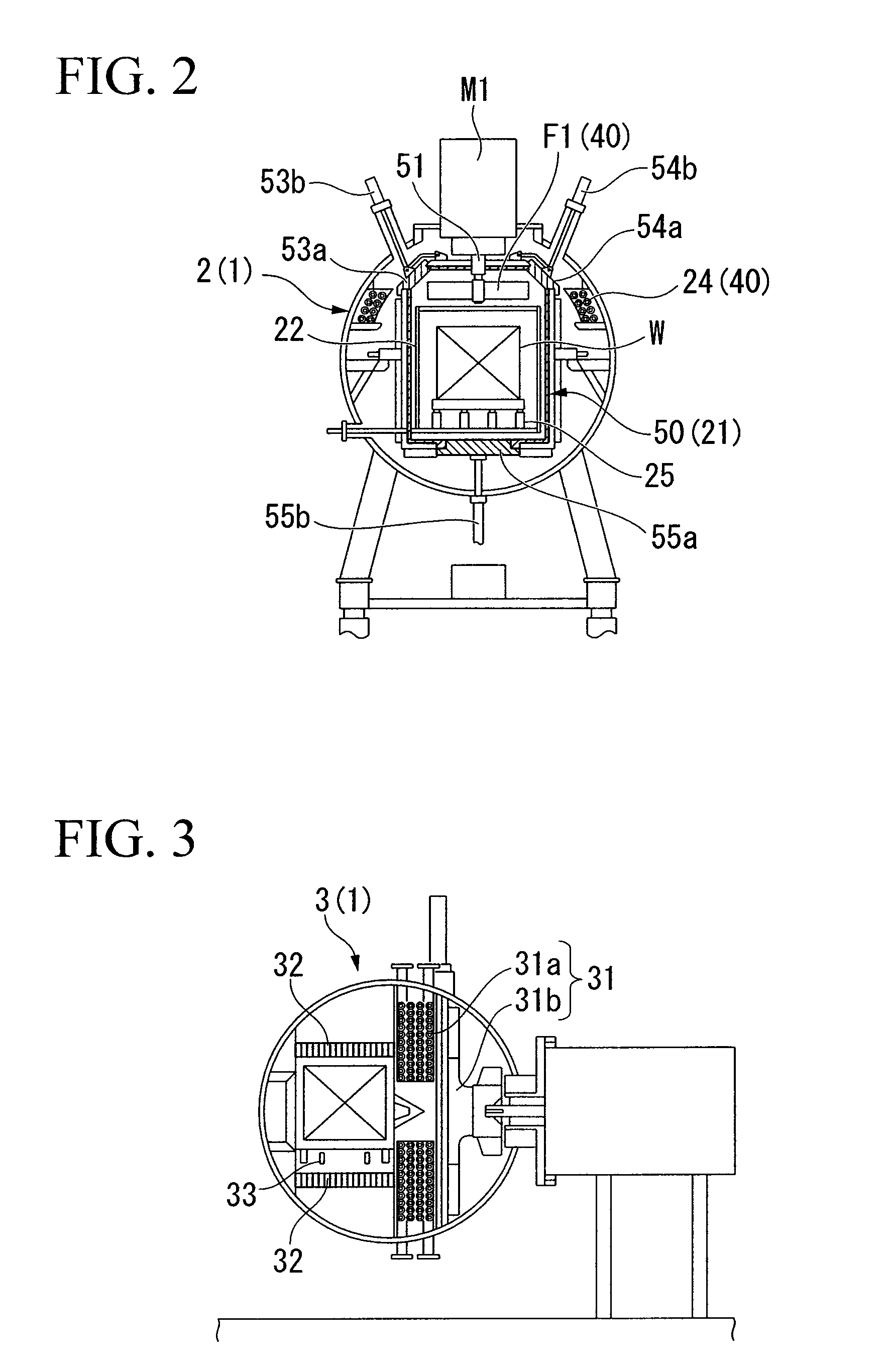
[0043]FIGS. 1 to 3 are sectional views illustrating a configuration of a vacuum carburization apparatus according to the embodiment, where FIG. 1 is a front view, FIG. 2 is a left side view, and FIG. 3 is a right side view. As shown in FIGS. 1 to 3, the vacuum carburization apparatus according to the embodiment includes a case 1, a heating chamber 2, and a cooling chamber 3. The vacuum carburization apparatus is a two-chamber type in which heating and cooling processes are performed in separate chambers, respectively. The case 1 has a substantially cylindrical shape, and the case 1 is installed so that an axis thereof is horizontal. The case 1 is divided at a substantially middle thereof in an axial direction, i...


PUM

PropertyMeasurementUnit
temperatureaaaaaaaaaa
depthaaaaaaaaaa

Abstract

There are provided a method, between a diffusion process and a quenching process, a normalizing process of performing step cooling in which a temperature lowering treatment and a temperature keeping treatment are alternately repeated plural times so that a temperature history from the first temperature to a predetermined temperature satisfies a predetermined condition; an after-normalizing maintaining process of maintaining the temperature of the whole workpiece for a predetermined time after the normalizing process so that the whole workpiece becomes the predetermined temperature, thereby producing fine crystal grains in the workpiece; and a reheating process of raising the temperature of the workpiece to the second temperature, after the after-normalizing keeping process. According to the invention, even when a process temperature is set high to make rapid progress of carburization and diffusion and thus the process time is shortened, uniformity in temperature is achieved between a surface and a inside of a workpiece by the high-temperature process and crystal grains are prevented from being coarse, thereby obtaining a workpiece having a predetermined property value.

Description

BACKGROUND OF THE INVENTION[0001]1. Field of the Invention[0002]Priority is claimed on Japanese Patent Application No. 2007-060498, filed Mar. 9, 2007, the content of which is incorporated herein by reference.[0003]The present invention relates to a vacuum carburization method and a vacuum carburization apparatus.[0004]2. Description of the Related Art[0005]Vacuum carburization is a carburization technique in which a surface layer of a metallic workpiece is carburized and quenched to enhance the hardness of the surface layer. Such vacuum carburization is described in Japanese Patent Application Laid-Open No. 8-325701 (hereinafter, referred to as Patent Document 1) and Japanese Patent Application Laid-Open No. 2004-115893 (hereinafter, referred to as Patent Document 2).[0006]In the vacuum carburization described in Patent Document 1, a workpiece is vacuum-heated in a heating chamber to a predetermined temperature, carburizing gas such as acetylene is supplied into the heating chamber...

Claims


Application Information

Patent Timeline
Patent Type & Authority Applications(United States)
IPC IPC(8): C23C8/20C21D1/773
CPCC23C8/22C23C8/20
Inventor KATSUMATA, KAZUHIKO
Owner IHI CORP
Learn More