Lightweight rammer
a rammer and light-weight technology, applied in the field of rammers, can solve the problems of general unavoidable phenomenon, unsuitable air transport, and heavy towed artillery pieces, and achieve the effects of reducing fatigue, saving weight, and increasing speed
- Summary
- Abstract
- Description
- Claims
- Application Information
AI Technical Summary
Benefits of technology
Problems solved by technology
Method used
Image
Examples
first embodiment
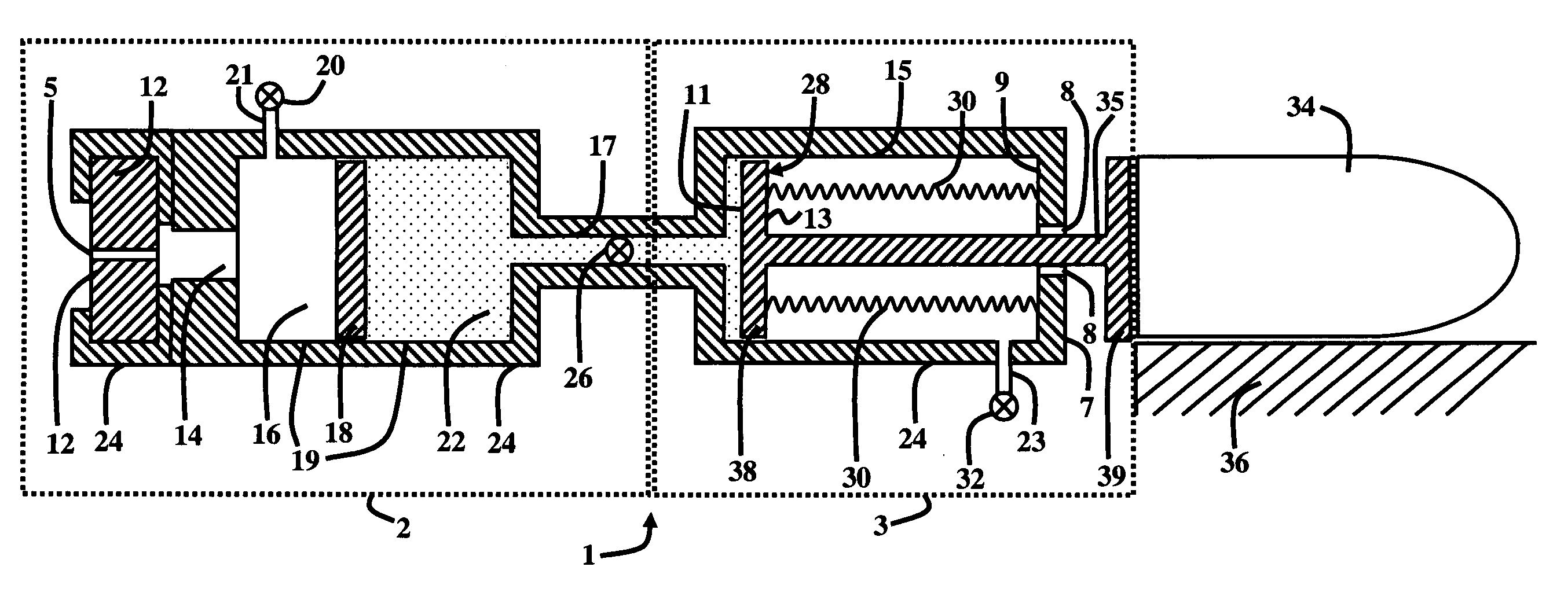
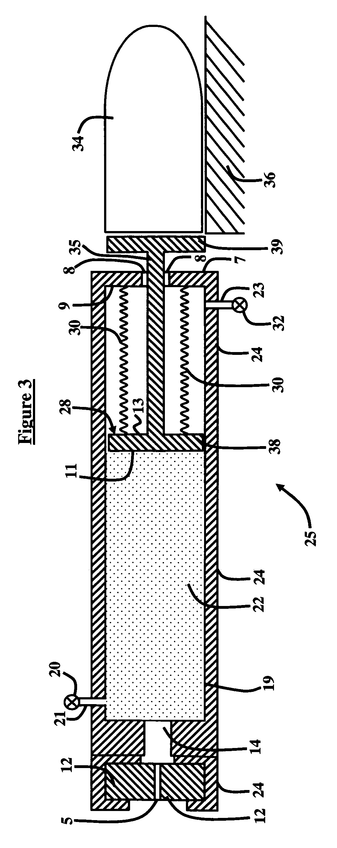
[0031]FIG. 1 illustrates an open cycle rammer system 1 according to the invention, whereby the open cycle rammer system 1 utilizes a source of working pressure and preferably uses an actuating fluid (gas or liquid) 22, but does not require external power supplies, motors, etc. Generally, the rammer system 1 comprises an internal combustion or monopropellant generator component 2 connected to a ramming component 3. More particularly, the rammer system 1 comprises an outer casing 24 which houses several sub-components. These sub-components include a firing mechanism 5, which is preferably embodied as a primer, catalyst, spark, or percussion or electric initiation-firing pin or probe.
[0032]The firing mechanism 5 engages a breech closure 12, which is preferably embodied as a horizontally guided sliding wedge. The breech closure 12 connects to a first side of an actuator component 14, wherein the actuator component 14 is embodied as a combustion chamber, a propellant cartridge, or a pres...
second embodiment
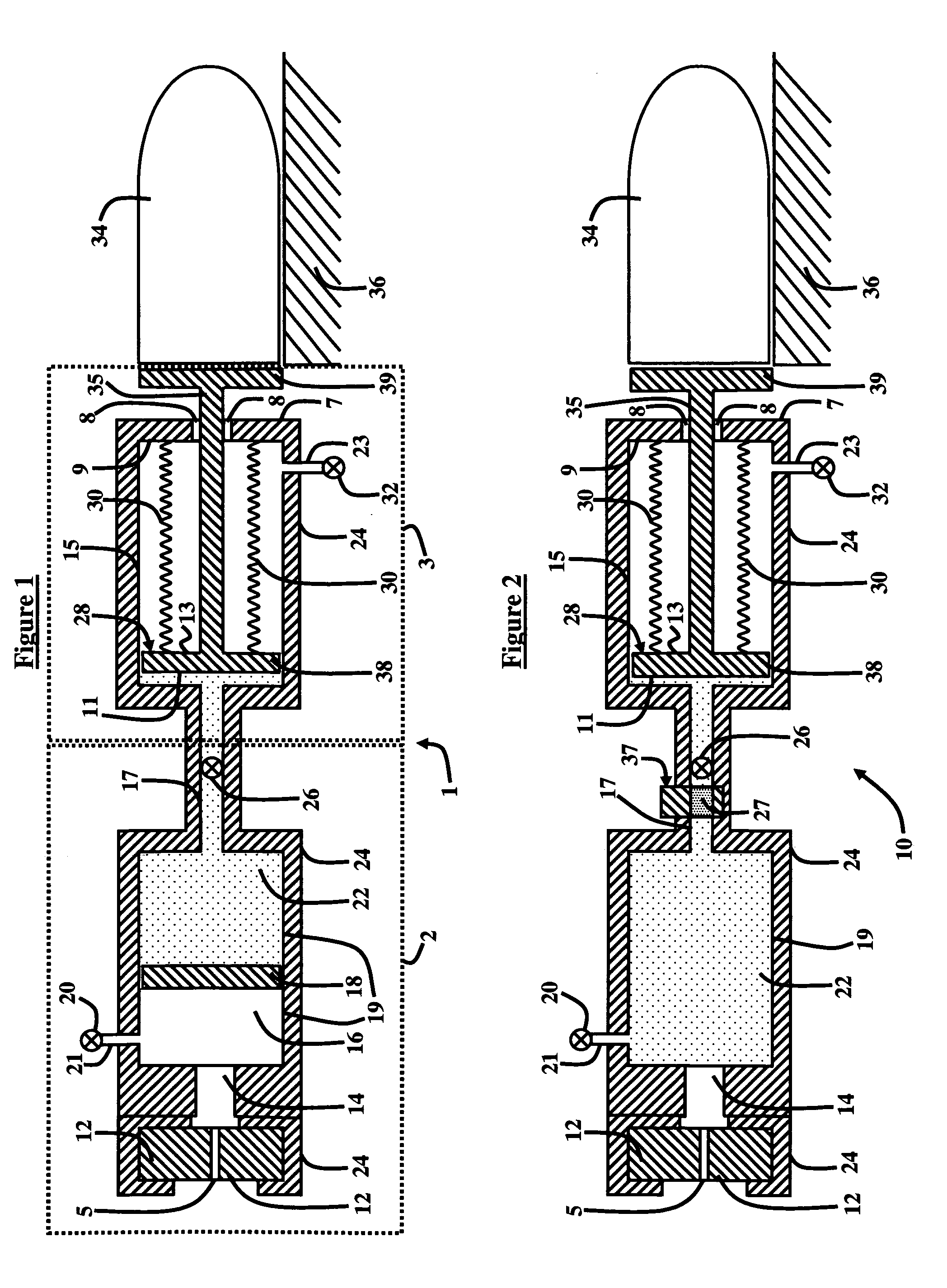
[0039]FIG. 2 illustrates an open cycle rammer assembly 10 with the direct action of propellant gases. The rammer assembly 10 is similarly configured to the open cycle rammer system 1 shown in FIG. 1, and as such like reference numerals in FIGS. 1 and 2 correspond to like components in both schematics. Generally, the rammer assembly 10 comprises an outer casing 24 which houses several sub-components. These sub-components include a firing mechanism 5, which is preferably embodied as a primer, spark, or percussion or electric initiation-firing pin or probe.
[0040]The firing mechanism 5 connects to a breech closure 12, which is preferably embodied as a horizontally guided sliding wedge. The breech closure 12 connects to a first side of an actuator component 14 embodied as a combustion chamber, a propellant cartridge, or a pressure vessel. On a second side of the actuator component 14 the rammer assembly 10 includes a pressure accumulator 19 which holds the actuating fluid 22. A vent 21 c...
fourth embodiment
[0044]FIGS. 4 through 7 illustrate successive stages of operation of a rammer system 31 according to the invention, which utilizes a regeneration piston 48 to regenerate the actuating fluid 22. Regeneration is accomplished through action of the regeneration piston 48 driven by the recoil motion of the recoiling parts (gun tube, breech, and cradle, collectively, the recoil mass 50) compressing the actuating fluid 22 vented from the rammer chamber 15 in retraction of the rammer piston 35. Generally, as shown in FIG. 4, high pressured gas 60 enters the pressure accumulator 19 from the actuator component 14 via a check valve 33 that separates the actuator component 14 from the pressure accumulator 19. The rammer system 31 further includes a second check valve 40 configured in the inner wall of the pressure accumulator 19, which connects to a regeneration cylinder 42 via a regeneration cylinder exit tube 41. The check valve 40 shown in FIG. 4 is closed to prevent the actuating fluid 22 f...
PUM
 Abstract
Description
Claims
Application Information
 - R&D
- Intellectual Property
- Life Sciences
- Materials
- Tech Scout
- Unparalleled Data Quality
- Higher Quality Content
- 60% Fewer Hallucinations
Browse by: Latest US Patents, China's latest patents, Technical Efficacy Thesaurus, Application Domain, Technology Topic, Popular Technical Reports.
© 2025 PatSnap. All rights reserved.Legal|Privacy policy|Modern Slavery Act Transparency Statement|Sitemap|About US| Contact US: help@patsnap.com


