
Method and apparatus for applying coating solution

Inactive Publication Date: 2008-09-04
FUJIFILM CORP
View PDF4 Cites 13 Cited by
  • Summary
  • Abstract
  • Description
  • Claims
  • Application Information

AI Technical Summary

Benefits of technology

[0012]The present invention was contrived in view of the aforementioned conditions. An object of the present invention is to provide a method and apparatus for applying a coating solution capable of forming a film having a uniform thickness from the beginning of application of the coating solution onto a web and suppressing irregular coating such as coating streak.
[0019]In the third aspect, a preferable moving speed of the first moving step (that is, the slot die is moved toward the web in order to initiate application of a coating solution) is defined. It is preferable that the moving speed falls within the range of 3 mm / sec to 20 mm / sec. This is because, if the moving speed is as low as less than 3 mm / sec, it is likely to form a bead having an uneven thickness in the die width direction (web width direction), with the result that the coating film likely differs in thickness in the web-width direction when application of a coating solution is initiated. In contrast, when the moving speed is as high as beyond 20 mm / sec, the bead may not be stably formed in the coating initiation process, with the result that a trouble such as interruption of coating-solution supply occurs. The more preferable range of the moving speed is 5 mm / sec to 10 mm / sec. Note that it is not necessary to keep the moving speed mentioned above within the entire moving zone from the stand-by position to the coating initiation position. It is sufficient that the moving speed falls within the aforementioned range in the zone from at least 5 mm to the coating initiation position.
[0025]This is because the present invention produces an excellent effect in forming a thin coating film having a wet-state film thickness of 24 μm or less.
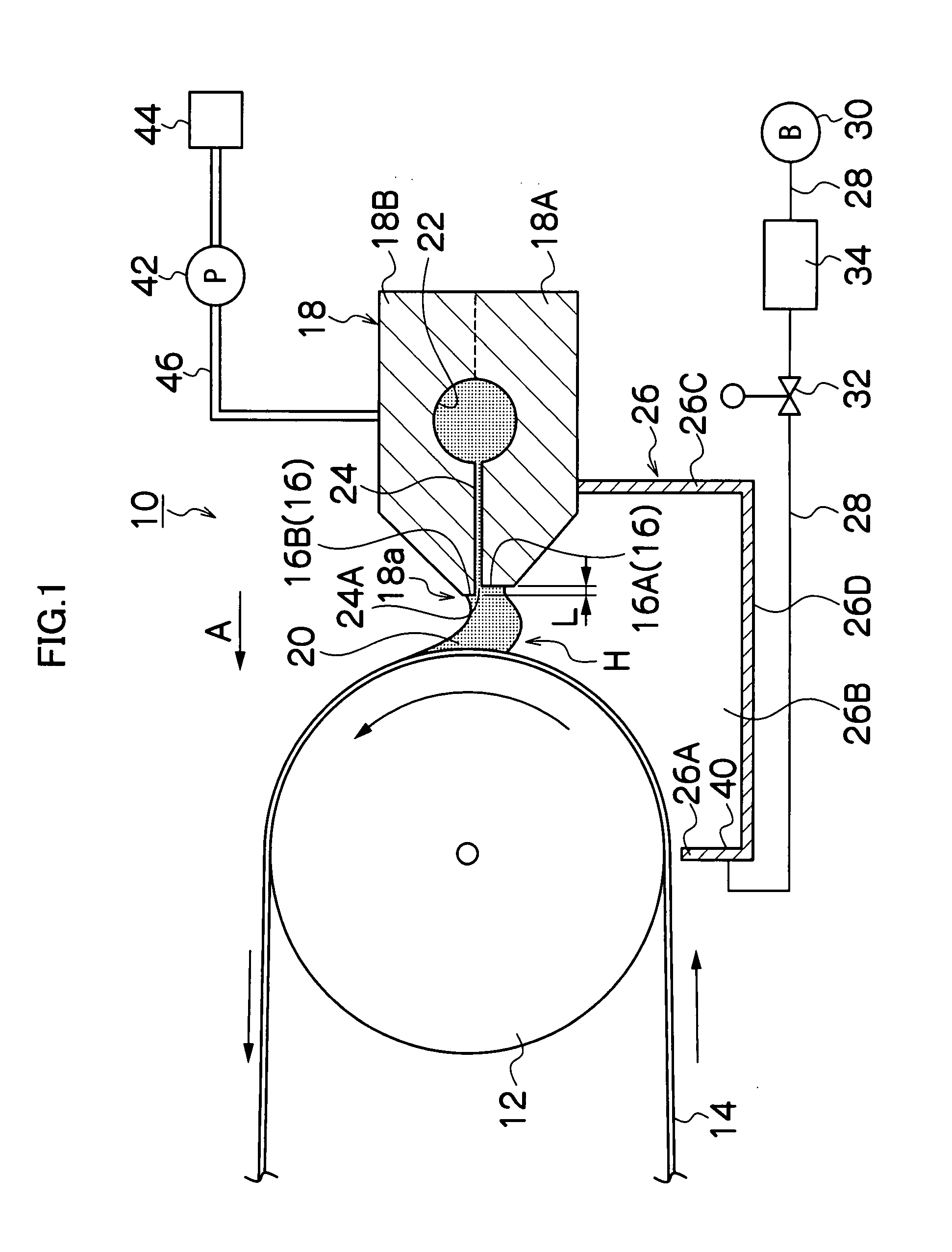
[0035]The tenth to twelfth aspects of the invention are directed to a coating apparatus to which the present invention is applied. Using the apparatus, application of a coating solution can be performed in two-stage moving operation. First, a small clearance than that of the standard coating process is employed for initiating application and then the clearance of the standard coating process is employed by moving the slot die. Therefore, a coating film having a uniform thickness can be formed from the beginning of the coating process while suppressing irregular coating such as coating streak; at the same time, the coating solution can be applied in accordance with the wet-state film thickness of the coating film to be formed.
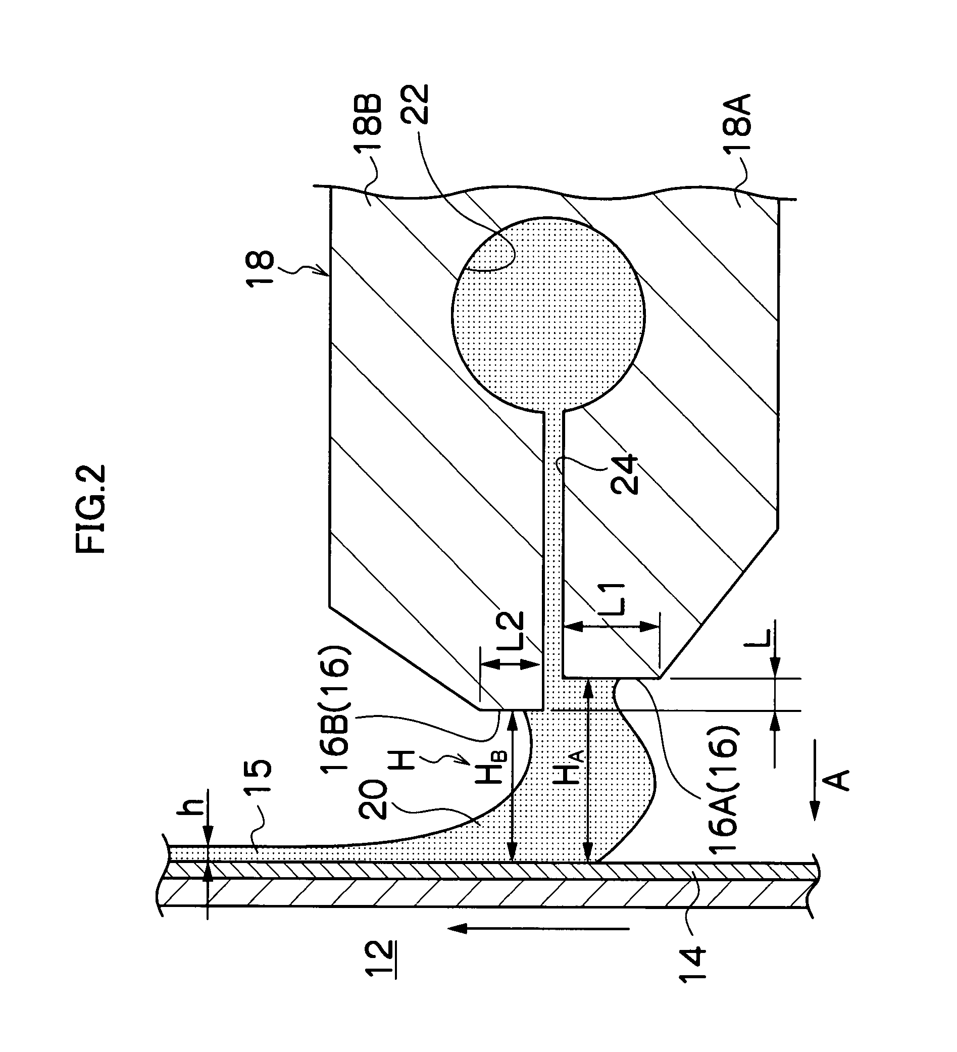
[0036]According to the method and apparatus for applying a coating solution of the invention, the clearance at the coating initiation process is smaller than the standard coating process. By virtue of this, the crosslink of a coating solution in the coating initiation process can be easily formed and the effect of vibration when a slot die moves can be suppressed. Hence, application of a coating solution can be effectively performed in accordance with the thickness of the film to be desired from initiation of the coating process.
[0037]Accordingly, the present invention is particularly effective for a method of manufacturing an optical film, which is a thin coating film requiring high dimensional accuracy.

Problems solved by technology

However, the coating methods of Japanese Patent Application Laid-Open Nos. 2003-236451 and 9-141169 have problems.
It is difficult to form a coating film with accuracy from the beginning of a coating process.
In particular, in the beginning of the coating process for a thin film, since a coating solution cannot be supplied continuously, the resultant coating film becomes non-uniform in thickness and has irregular coating such as coating streak.

Method used


Image

  • Method and apparatus for applying coating solution
  • Method and apparatus for applying coating solution
  • Method and apparatus for applying coating solution

Examples


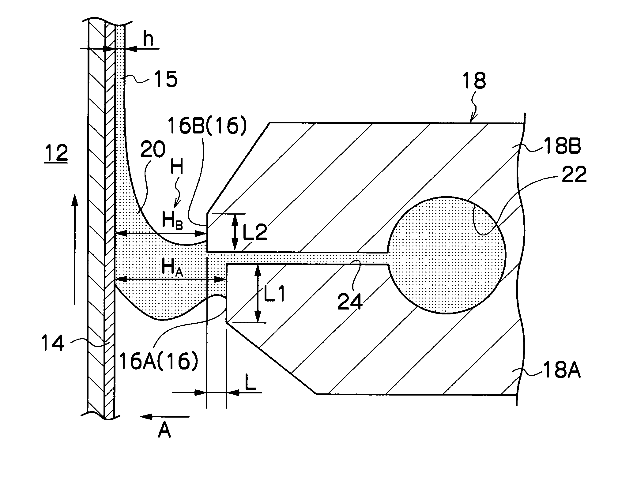
example 1

[0105]In Tests 1 to 23 of Example 1, the coating method of the present invention was performed using the coating apparatus of the present invention by changing various factors as mentioned below. The form and state of the bead at the coating initiation process, at which the coating solution shown below was applied onto a web, and the state of the coating film formed on the web were observed and evaluated. Evaluation results were shown by evaluation scores: E (excellent), G (good), NG (no good), and P (poor).

[0106]Evaluation score E denotes that a bead of a coating solution was formed in the clearance from the coating initiation process; no irregular coating such as coating streak was observed on the coating surface; and the dimensional accuracy of the resultant film with respect to thickness is less than ±0.5% relative to a reference desired film-thickness.

[0107]Evaluation score G denotes that a bead of a coating solution was formed in the clearance from the coating initiation proce...

example 2

[0121]In Example 2, Test 24 to 36, 41, 42 and 44 were performed by changing the conditions: the wet-state thickness h of a film formed of a coating solution applied onto a web, coating speed (moving speed of a web), the viscosity of the coating solution, and surface tension of the coating solution, while satisfying preferable ranges of the factors (A), (B), (C) and (D) of Example 1.

[0122]For comparison, Tests 37 to 40 and 43 were performed which were all outside the preferable range with respect to factor (A), that is, the ratio H2 / H1 was 1.0.

[0123]The test results are shown in FIG. 7. In Tests 24 to 27, the viscosity of a coating solution is changed. In Tests 28 to 30, the surface tension of a coating solution is changed. In Tests 31 to 34 and 37 to 44, the wet-state thickness h of a coating film is changed. In Tests 35 and 36, a coating speed is changed.

[0124]As is apparent from FIG. 7, in Tests 24 to 36, 41, 42, 44, as long as preferable ranges of factors (A), (B), (C) and (D) of...

example 3

[0125]In Example 3, the coating conditions of Table 1 were changed to those shown in Table 2.

TABLE 2Coating speed60m / minWet-state film thickness h of coating film7.0μmCoating width1200mmDownstream-side clearance70μmOverbite amount70μmDownstream lipland length60μmSlot width140μmMaterial for width-regulating boardSUS630Degree of vacuum of vacuum chamber950PaMaterial for webTriacetylcellulose (TAC)

[0126]Of the factors (A), (B), (C) and (D) of Example 1, only factor (A) was changed in this Example. A ratio of H2 / H1 is 0.86 in Test 45, 1.0 in Test 46 and 1.1 in Test 47.

[0127]The test results are shown in FIG. 8. As is apparent from FIG. 8, in Test 45 where a first moving step where coating is started by moving a slot die to the coating initiation position (a) (the clearance H2 at the coating initiation process is lower than the clearance H1 at the standard coating process) and a second moving step where the slot die is moved to the standard coating position (b) having the clearance H1 in...


PUM


Abstract

The present invention provides a method for applying a coating solution by discharging a coating solution from a slit provided at a tip of a slot-die toward a surface of a web fitted onto a backup roller, the method comprising: a stand-by step of staying the slot-die at a stand-by position having a larger clearance between the slot-die and the web than that of a standard coating process; and a two-stage moving operation including a first moving step in which the slot die is moved to a coating initiation position having a smaller clearance than that of the standard coating process to initiate application of a coating solution, and a second moving step in which the slot die is moved away from the coating initiation position to a standard coating position having the clearance of the standard coating process to perform constant application of the coating solution.

Description

BACKGROUND OF THE INVENTION[0001]1. Field of the Invention[0002]The present invention relates to a method and apparatus for applying a coating solution, and more particularly, a coating initialization technique for accurately and stably forming a thin coating film such as an optical film from the beginning of a coating process.[0003]2. Description of the Related Art[0004]Conventionally, as an apparatus for forming a coating film (coating layer) having a desired thickness on a surface of a web (belt-form substrate), a bar coater system, reverse roll coater system, gravure roll coater system and slot die coater system such as extrusion coater, etc. are known. Of the apparatuses of these systems, the coating apparatus of the slot die coater system is advantageous over other systems because a thin coating film can be obtained at a high speed. By virtue of the advantage, the coating apparatus of the slot die coater system has been widely used in various fields of coating.[0005]In the slo...

Claims


Application Information

Patent Timeline
IPC IPC(8): B05D5/06B05D1/30B05C5/00
CPCB05D1/265B05C5/0254
Inventor OKI, KAZUHIROSONOBE, MASAKI
Owner FUJIFILM CORP
Learn More