
Apparatus for measuring iq imbalance

a technology of iq imbalance and apparatus, which is applied in the direction of transmission monitoring, dc level restoring means or bias distortion correction, and baseband system details, etc., can solve the problems of gain imbalance, phase imbalance, and iq imbalance in a real iq mixer, so as to prevent the effect of noise generation and simplify the measuring process

Active Publication Date: 2008-09-04
GCT SEMICONDUCTOR INC
View PDF23 Cites 24 Cited by
  • Summary
  • Abstract
  • Description
  • Claims
  • Application Information

AI Technical Summary

Benefits of technology

[0010]Another object of the application is to provide an apparatus for measuring an IQ imbalance wherein an output signal of an IQ up-conversion mixer is inputted to an IQ down-conversion mixer rather than measuring the IQ imbalance using a signal received through a wireless communication thereby simplifying the measuring process, and preventing an effect of a noise generated in wireless communication.

Problems solved by technology

However, an IQ imbalance occurs in a real IQ mixer.
The IQ imbalance can include a gain imbalance that occurs because amplitudes of an in-phase signal and a quadrature signal transmitted from a local oscillator to the IQ mixer are not identical, and a phase imbalance that occurs because the in-phase signal and the quadrature signal do not have a phase difference of 90°.
When the IQ imbalance occurs, an output of the IQ mixer includes an undesirable noise component, which can result in a degradation of a signal-to-noise ratio.
However, since IQ imbalance is measured using the received signal in accordance with the method disclosed by the patents, an accuracy of the measured IQ imbalance is degraded because of noise of a wireless channel included in the received signal.
However, the technique disclosed by the patent requires a separate test signal and / or does not disclose a Tx IQ.

Method used


Image

  • Apparatus for measuring iq imbalance
  • Apparatus for measuring iq imbalance
  • Apparatus for measuring iq imbalance

Examples


Embodiment Construction

[0028]Embodiments according to the present general inventive concept will be described with reference to the accompanying drawings. Such embodiments are exemplary and not to be construed as limiting. The interpretations of the terms and wordings used in description and claims should not be limited to common or literal meanings. Many alternatives, modifications, and variations will be apparent to those skilled in the art.

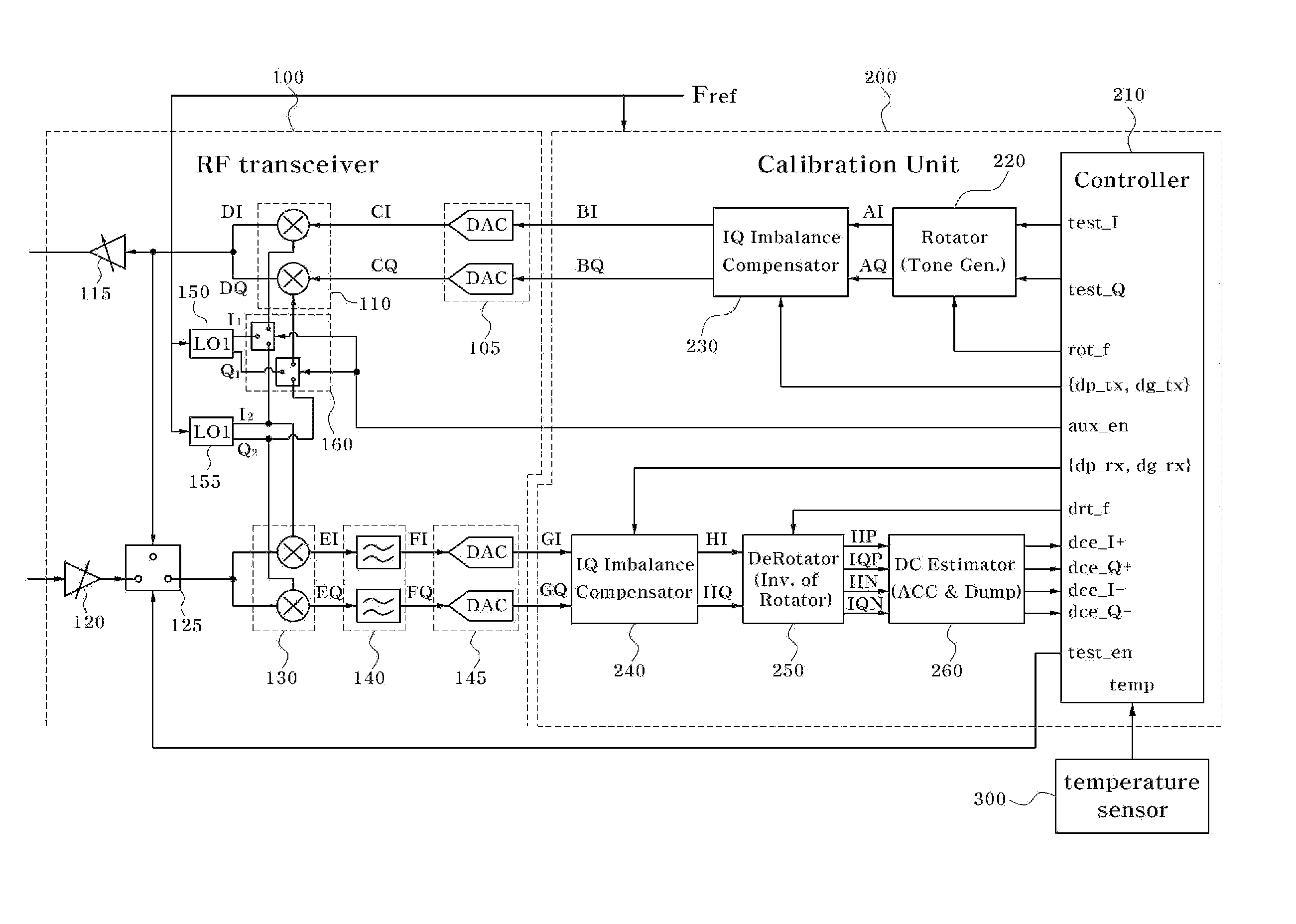
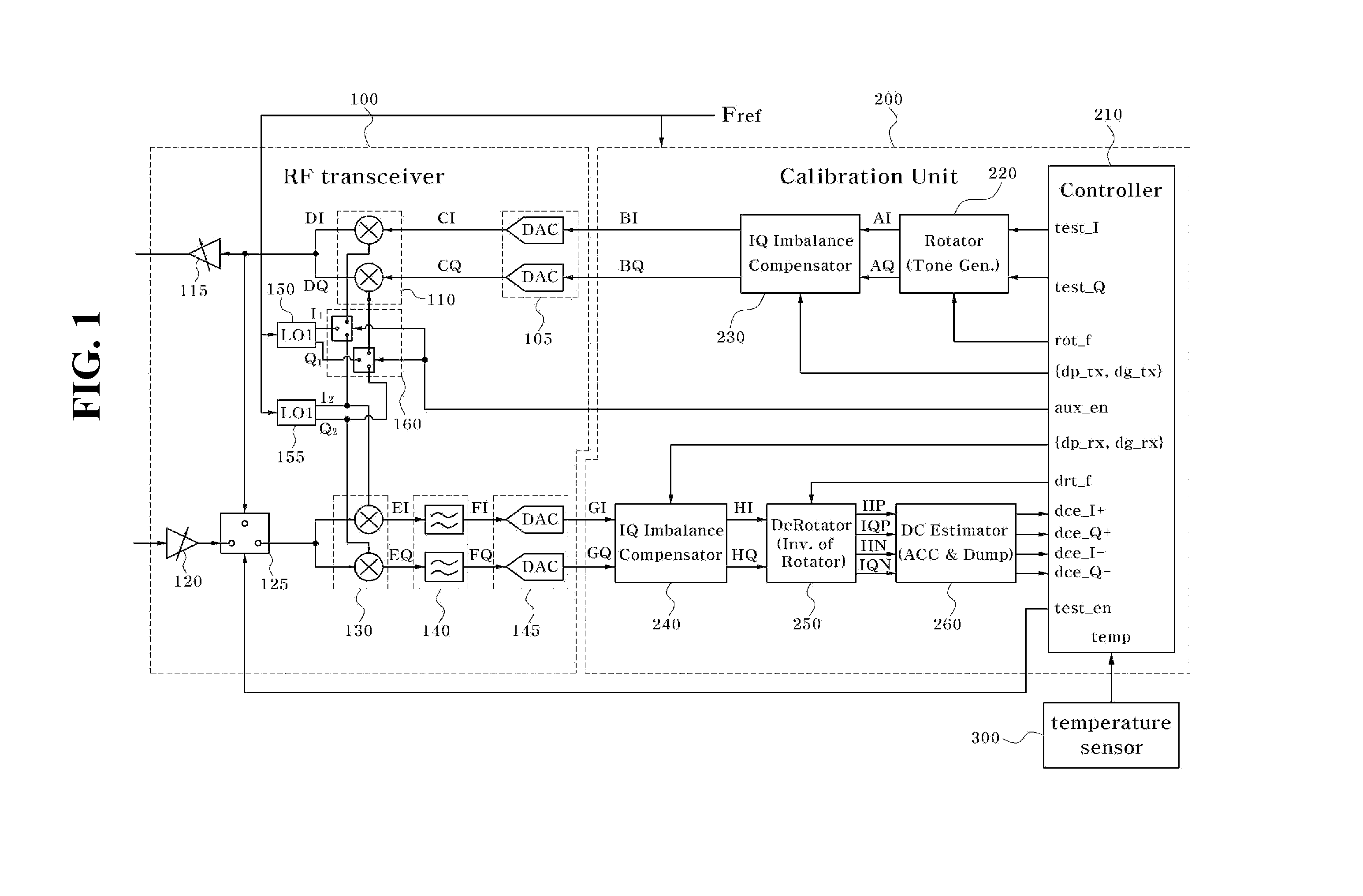
[0029]FIG. 1 is a diagram illustrating a transceiving circuit in accordance with a an embodiment of the application. As illustrated to FIG. 1, the transceiving circuit can include an RF transceiver 100 and a calibration unit 200.

[0030]The RF transceiver 100 can include an IQ DAC (IQ digital-to-analog converter) 105, an IQ up-conversion mixer 110, a power amplifier 115, a low noise amplifier 120, a feedback switch 125, an IQ down-conversion mixer 130, an IQ filter 140, an IQ ADC (IQ analog-to-digital converter) 145, a first local oscillator 150, a second local oscilla...


PUM


Abstract

The present general inventive concept relates to apparatuses and / or methods for measuring an IQ imbalance. In one embodiment, a signal generator can provide a first IQ signal of a DC component during a first period and the first IQ signal of a first angular frequency during a second period, an IQ up-conversion mixer can up-convert the first IQ signal by a second angular frequency during the first period and up-convert the first IQ signal by a third angular frequency during the second period to output a second IQ signal, an IQ down-conversion mixer can down-convert the second IQ signal by the third angular frequency to output a third IQ signal and an IQ imbalance detector can obtain a first IQ imbalance (e.g., Rx IQ imbalance) from the third IQ signal during the first period and a second IQ imbalance (e.g., Tx / Rx IQ imbalance) during the second period.

Description

[0001]This application claims priority under 35 U.S.C. §119 (a) of Korean Patent Application No. 10-2007-0013042, filed on Feb. 8, 2007, in the Korean Intellectual Property Office, the disclosure of which is incorporated herein by reference in its entirety.1. FIELD OF THE INVENTION[0002]The present general inventive concept relates to an apparatus for measuring an IQ imbalance.2. BACKGROUND OF THE INVENTION[0003]A technique for converting a base band signal (hereinafter referred to as “BB signal”) or an intermediate frequency signal (hereinafter referred to as “IF signal”) to a radio frequency signal (hereinafter referred to as “RF signal”) using an IQ mixer or a technique for converting the RF signal to the BB signal or the IF signal is widely used in a field of a wireless communication.[0004]However, an IQ imbalance occurs in a real IQ mixer. The IQ imbalance can include a gain imbalance that occurs because amplitudes of an in-phase signal and a quadrature signal transmitted from ...

Claims


Application Information

Patent Timeline
Patent Type & Authority Applications(United States)
IPC IPC(8): H04L25/06H04B17/00H04B3/46H04Q1/20
CPCH03D3/009H03D7/166H04L2027/0016H04L27/364H04L27/3863H04L25/061H04L7/00
Inventor LEE, KYEONGHOPARK, JOONBAELEE, JEONG WOOLEE, SEUNG-WOOKLEE, EAL WAN
Owner GCT SEMICONDUCTOR INC
Learn More