
Medical Communication System and its Communication Method

a communication system and medical technology, applied in the field of medical communication system, can solve the problems that the processor must be moved in the hospital, and achieve the effect of reducing the time and effort for attaching/detaching cables and removing constraints on the installation of instruments

Inactive Publication Date: 2008-08-28
OLYMPUS CORP
View PDF4 Cites 13 Cited by
  • Summary
  • Abstract
  • Description
  • Claims
  • Application Information

AI Technical Summary

Benefits of technology

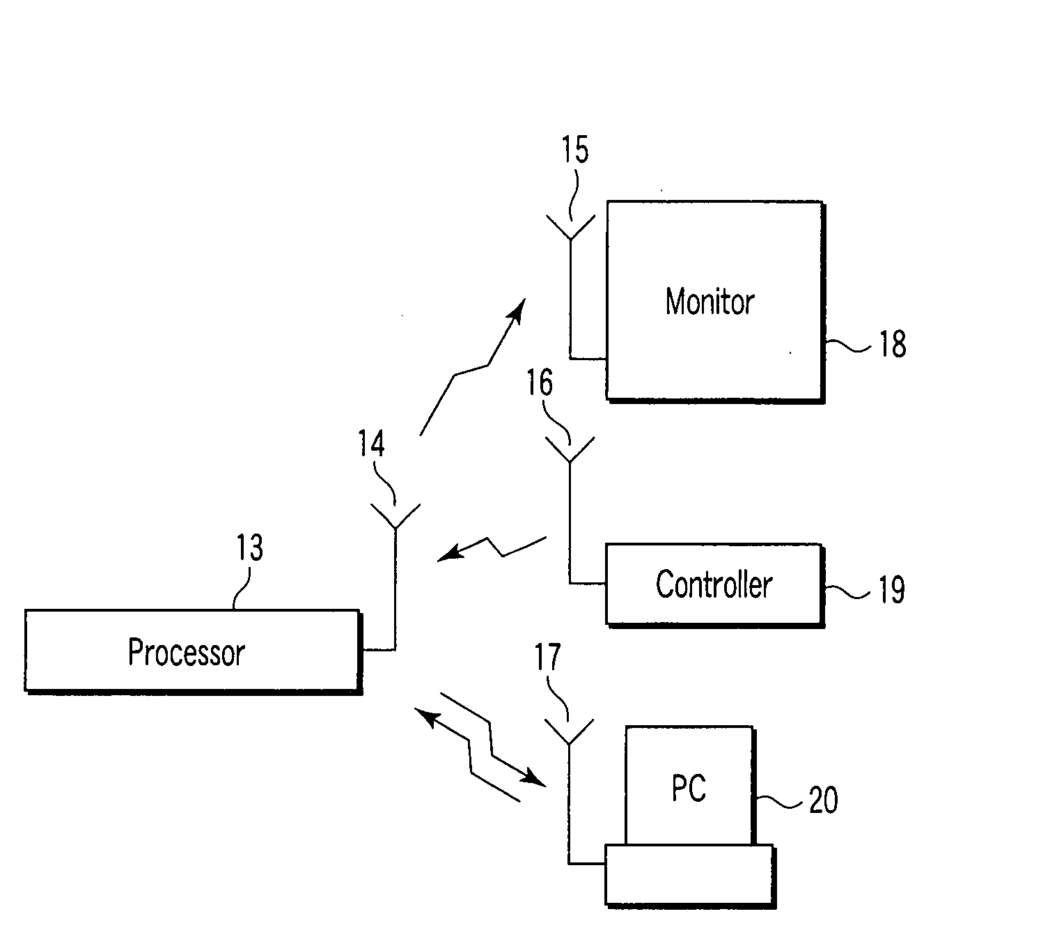
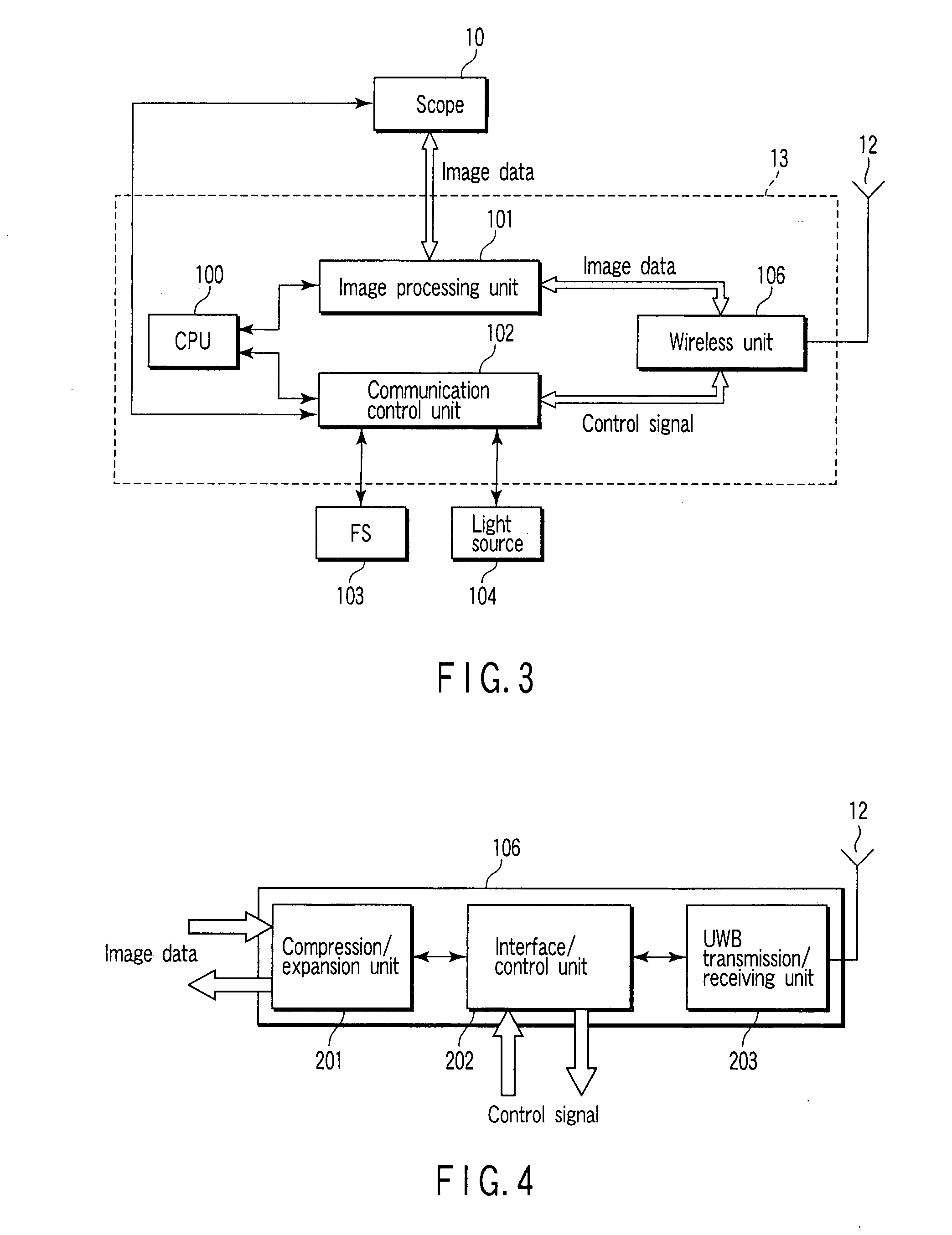
The present invention provides a medical communication system and its communication method for connecting a medical instrument with a processor using radio signals. This eliminates the need for troublesome movements of cables and constraints on the installation of instruments. The system includes a medical instrument with an image pickup element, a processor with an image processing section, and a peripheral unit for performing preset processing using the image signal processed by the processor. The processor and peripheral unit can communicate with each other using a UWB wireless transmission system. The communication method includes fetching an image signal, executing image processing, and transmitting the processed image signal with a control signal for controlling communication with the peripheral unit using UWB wireless transmission system. The technical effects of the invention include improved convenience and efficiency in medical surgery procedures using endoscopy.

Problems solved by technology

When performing various types of medical surgery using an endoscope, troublesome movements of a processor must be done in a hospital.

Method used


Image

  • Medical Communication System and its Communication Method
  • Medical Communication System and its Communication Method
  • Medical Communication System and its Communication Method

Examples


Embodiment Construction

[0021]Embodiments of the invention will be descried in detail with reference to the accompanying drawings.

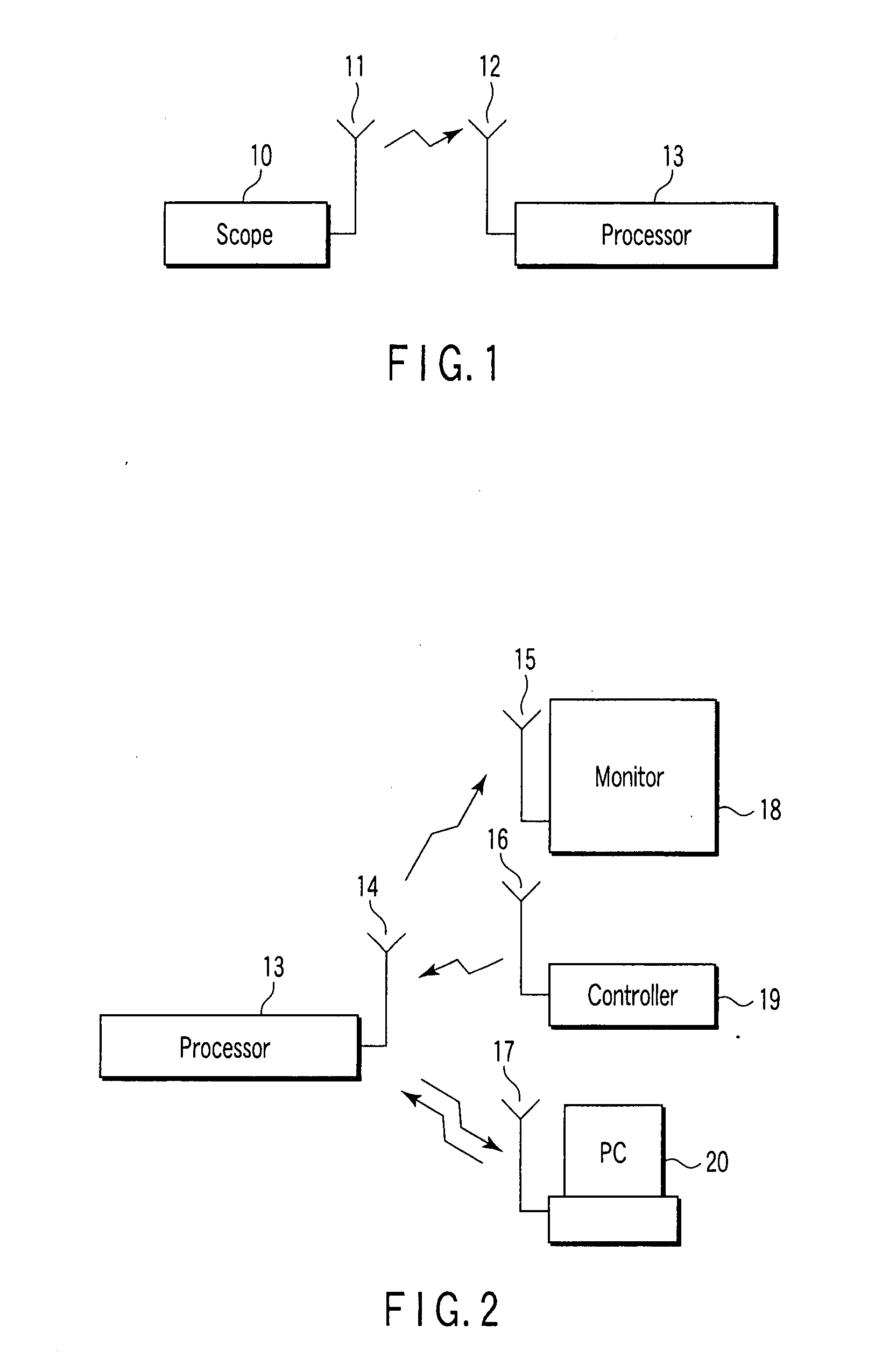
[0022]FIG. 1 is a view illustrating the configuration of a wireless transmission system according to a first embodiment of the invention. The first embodiment is characterized in that signals are transmitted by radio via antennas 11 and 12 between a processor 13 for image processing and a scope 10 as a medical instrument, which is inserted for observation into the body cavity of a patient and contains an image pickup element, such as a CCD (charge-coupling device). In this wireless transmission, it is assumed that image data obtained by the scope 10 is transmitted to the processor 13. Further, compact antennas such as dipole antennas are suitable as the antennas 11 and 12.

[0023]With the above configuration, the scope 10 can be moved freely, which the constraints on the installation of the instruments can be eliminated, and the time and effort for attaching / detaching, for example...


PUM


Abstract

A medical communication system is provided with a scope 10 including an image pickup element, and a processor 13 including an image processing section which performs image processing on an image signal obtained by the image pickup element. The processor 13 further includes a communication control section which controls communication with the medical instrument. The scope 10 and the processor 13 are connectable by radio.

Description

TECHNICAL FIELD[0001]The present invention relates to a medical communication system and its communication method.BACKGROUND ART[0002]In currently available electronic endoscope systems, a scope section as an imaging unit is connected via a cable to a processor as an image processing unit. Further, the processor is connected via a cable to a peripheral device, such as a monitor / printer as a display / record unit. Jpn. Pat. Appln. KOKAI Publications Nos. 2003-190087 and 6-296589 disclose such electronic endoscope systems.DISCLOSURE OF INVENTION[0003]When performing various types of medical surgery using an endoscope, troublesome movements of a processor must be done in a hospital. Concerning, for example, troublesome transfer of the cables of a processor monitor and peripheral devices, and troublesome attachment / detachment of the cables, which must be performed for moving the processor, or constraints on the installation of the instruments, there is a demand for improvements from users...

Claims


Application Information

Patent Timeline
Patent Type & Authority Applications(United States)
IPC IPC(8): H04B7/24
CPCA61B1/00016A61B5/0013H04N7/183
Inventor IJICHI, TOSHIROTAKAHASHI, KAZUMASASUZUKIONO, YASUHIRO
Owner OLYMPUS CORP
Learn More