
Gas sensor apparatus for automotive exhaust gas applications

Inactive Publication Date: 2008-08-28
HONEYWELL INT INC
View PDF48 Cites 15 Cited by
  • Summary
  • Abstract
  • Description
  • Claims
  • Application Information

AI Technical Summary

Benefits of technology

[0010]It is another aspect of the present invention to provide for a gas sensor apparatus that avoids breakage of the utilized sensor element.
[0011]It is another aspect of the present invention to provide for a gas sensor packaging apparatus that in which thermal loss is minimized.
[0013]The aforementioned aspects and other objectives and advantages can now be achieved as described herein. A gas sensor apparatus and method of forming the same are disclosed herein. The gas sensor apparatus generally includes a gas sensor element comprising a heater and a plurality of electrodes. Additionally, a ceramic substrate can be provided for supporting the plurality of electrodes on one side of the ceramic substrate and the heater on an opposite side of the ceramic substrate. The gas sensor element is preferably embedded in the ceramic substrate. The ceramic substrate also possesses a substantially circular shape in order to prevent a breakage of the gas sensor element, avoid thermal loss, and permit the gas sensor apparatus to withstand mechanical shock and high vibrations while occupying a minimal packaging space.
[0015]The gas sensor element also includes at least one platinum conductive pad. The plurality of contact terminals can be resistance-welded to the ceramic substrate. The heater also maintains the temperature of the gas sensor element. Additionally, the metallic housing can be configured to include an outer baffle and an inner baffle provided in the metallic housing, thereby covering a gas exposed portion of the gas sensor element. The inner baffle forms a cup-like groove towards the gas sensor element. Additionally, an embossed feature can be provided, which assists a flow of gas flow near the gas sensor element.
[0016]The disclosed gas sensor apparatus is based an innovative packaging design that avoid breakage of the sensor element, while the substrate shape can be circular with one side constituting a heater side and the other side functioning as sensor side. The contact pads can be screen-printed, while the contact terminals can be resistance-welded or any other suitable joining process to one or more of the contact pads. To minimize thermal loss, the substrate has a minimum contact surface with the housing and can be designed for less operating power. The sensor occupies less space as the sensor element size is minimized according to such a design. The circular ceramic substrate generally includes a platinum heater on one side (i.e., the heater side) and platinum electrodes on the other side, which provide for printing sensing material such as a metal oxide semiconductor.

Problems solved by technology

Since the configuration is planar and thinner, the possibility of breakage due to vibration and mechanical shock is very high.
These factors are difficult to achieve.

Method used


Image

  • Gas sensor apparatus for automotive exhaust gas applications
  • Gas sensor apparatus for automotive exhaust gas applications
  • Gas sensor apparatus for automotive exhaust gas applications

Examples


Embodiment Construction

[0027]The particular values and configurations discussed in these non-limiting examples can be varied and are cited merely to illustrate at least one embodiment and are not intended to limit the scope thereof.

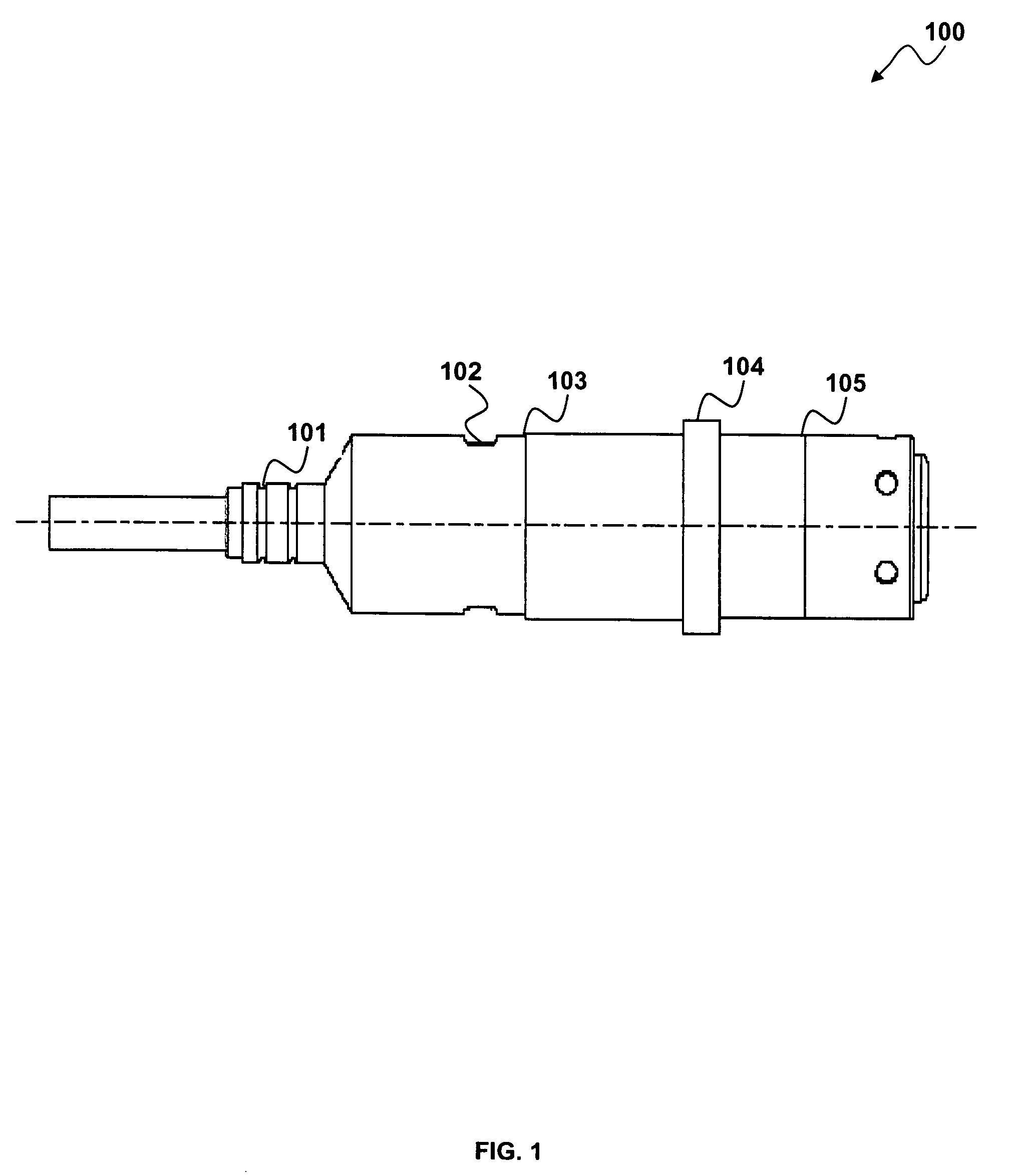
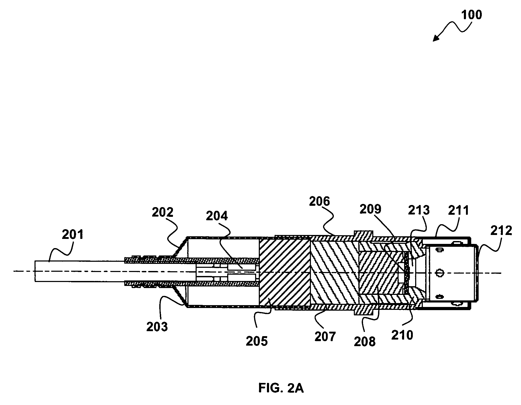
[0028]FIG. 1 illustrates a side view of a gas sensor apparatus 100, which can be implemented in accordance with a preferred embodiment. FIG. 2A illustrates a longitudinal cross-sectional view of the gas sensor apparatus 100 as depicted in FIG. 1, in accordance with a preferred embodiment. The gas sensor apparatus 100 generally includes an embossing 102, a laser welding 103, a collar 104, and a welding 105. The gas sensor apparatus 100 includes a crimping 101 to seal the cable 201 as depicted in FIG. 2A, and an embossing 102 to retain a ceramic insulator 205 as also depicted in FIG. 2A and laser welding 103 of a rear cover 202 with a main shell 206 as further depicted in FIG. 2A. The gas sensor apparatus 100 also includes a collar 104 located in a portion of the main shell 206 a...


PUM

PropertyMeasurementUnit
Temperatureaaaaaaaaaa
Flow rateaaaaaaaaaa
Electrical conductoraaaaaaaaaa

Abstract

A gas sensor apparatus and method of forming the same generally includes a gas sensor element comprising a heater and a plurality of electrodes. A ceramic substrate can be provided for supporting the electrodes on one side of the ceramic substrate and the heater on the opposite side of the ceramic substrate. The gas sensor element is preferably embedded in the ceramic substrate. The ceramic substrate also possesses a substantially circular shape in order to prevent a breakage of the gas sensor element, avoid thermal loss, and permit the gas sensor apparatus to withstand mechanical shock and high vibrations while occupying a minimal package space.

Description

TECHNICAL FIELD[0001]Embodiments are generally related to sensor methods and systems. Embodiments are also related to gas sensors. Embodiments are additionally related to gas sensor packaging devices, systems and methods of forming the same.BACKGROUND OF THE INVENTION[0002]Sensors are often utilized in association with internal combustion engines to measure operating parameters and constituents of a resulting feed stream. For example, an exhaust gas sensor in a control system of an internal combustion engine can be used to measure the parameter of air / fuel ratio, CO, CO2, NOx etc. It is important to determine the gas concentration of exhaust gas in order to control the emission of an automotive engine. A control system can then use this information to control the engine parameters and thereby allow for minimum emissions.[0003]An engine controller can then employ the air / fuel ratio information to control the feed stream that flows through the engine and into an after treatment device...

Claims


Application Information

Patent Timeline
IPC IPC(8): B32B5/02
CPCG01N27/12Y10T29/49004Y10T29/49002
Inventor THANIGACHALAM, PALANISELVAN, THIRUMANI A.
Owner HONEYWELL INT INC
Learn More