
Fiber optic drop terminals for multiple dwelling units

a technology of fiber optic drop terminals and fiber optics, which is applied in the field of fiber drop terminals, can solve the problems of large fdts, generally not desirable for installation, and relatively expensive production, and achieve the effect of convenient and secure access, small “footprint” (area/volume) and convenient installation and servi

Inactive Publication Date: 2008-08-28
CORNING OPTICAL COMM LLC
View PDF17 Cites 114 Cited by
  • Summary
  • Abstract
  • Description
  • Claims
  • Application Information

AI Technical Summary

Benefits of technology

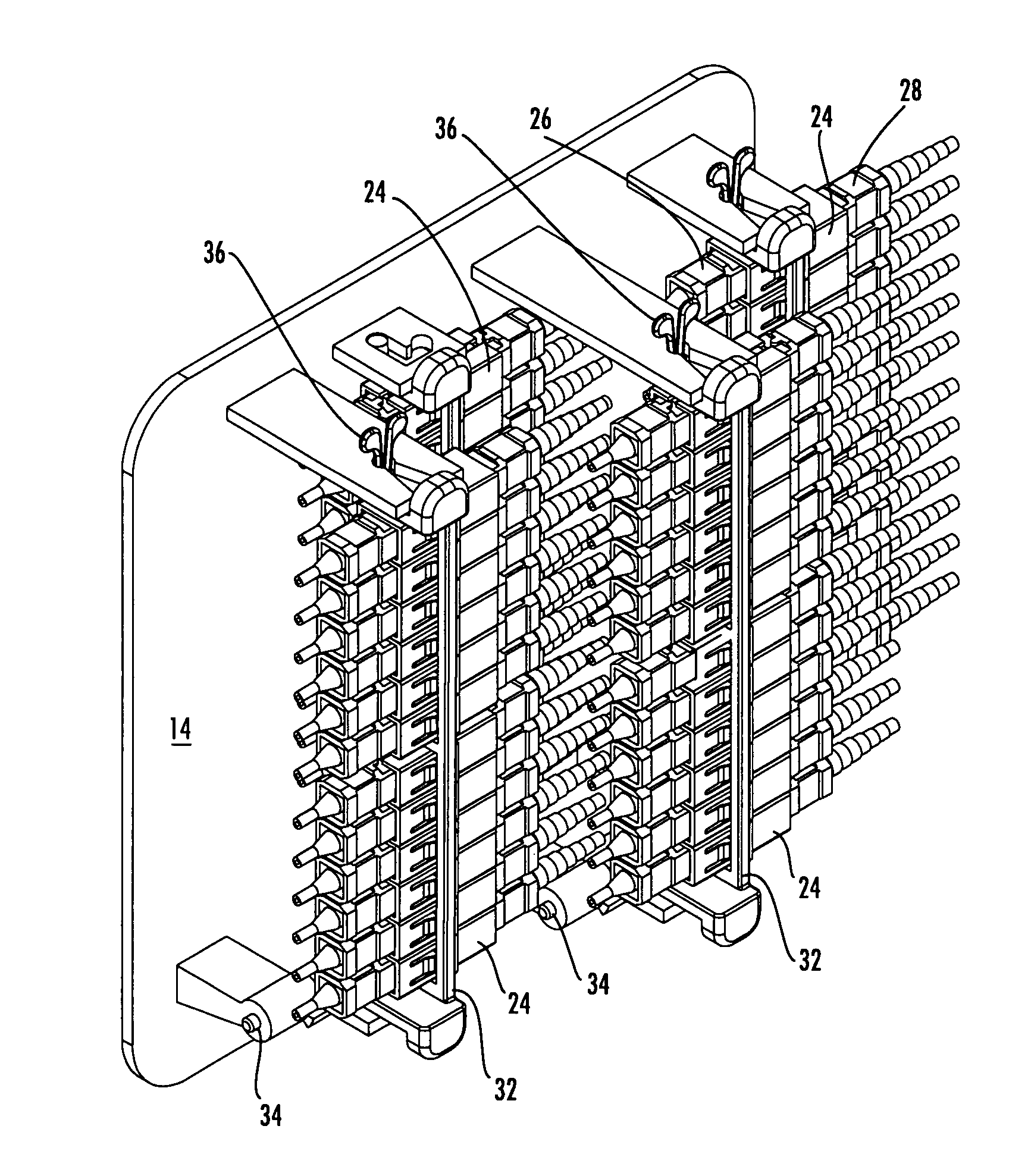
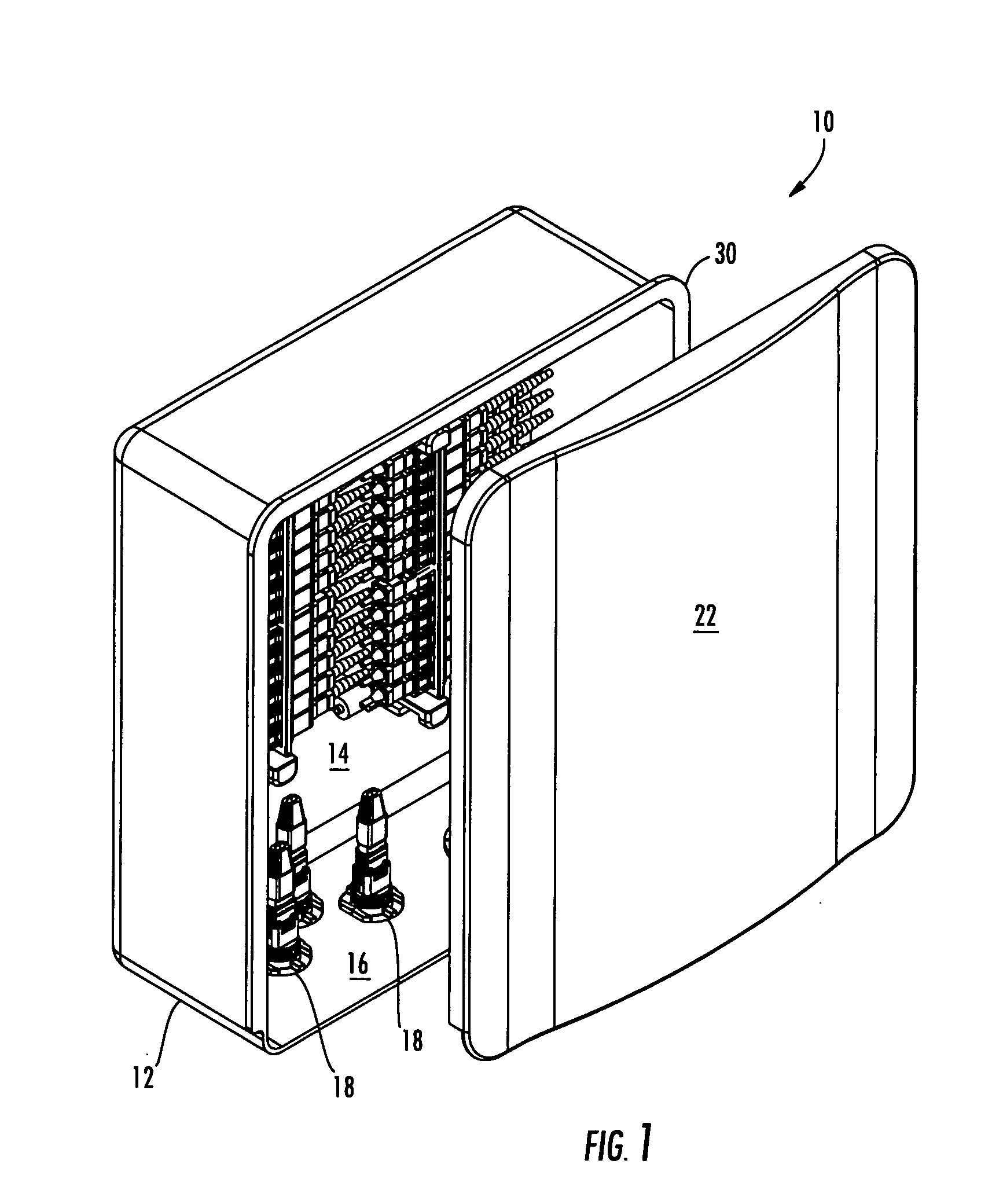
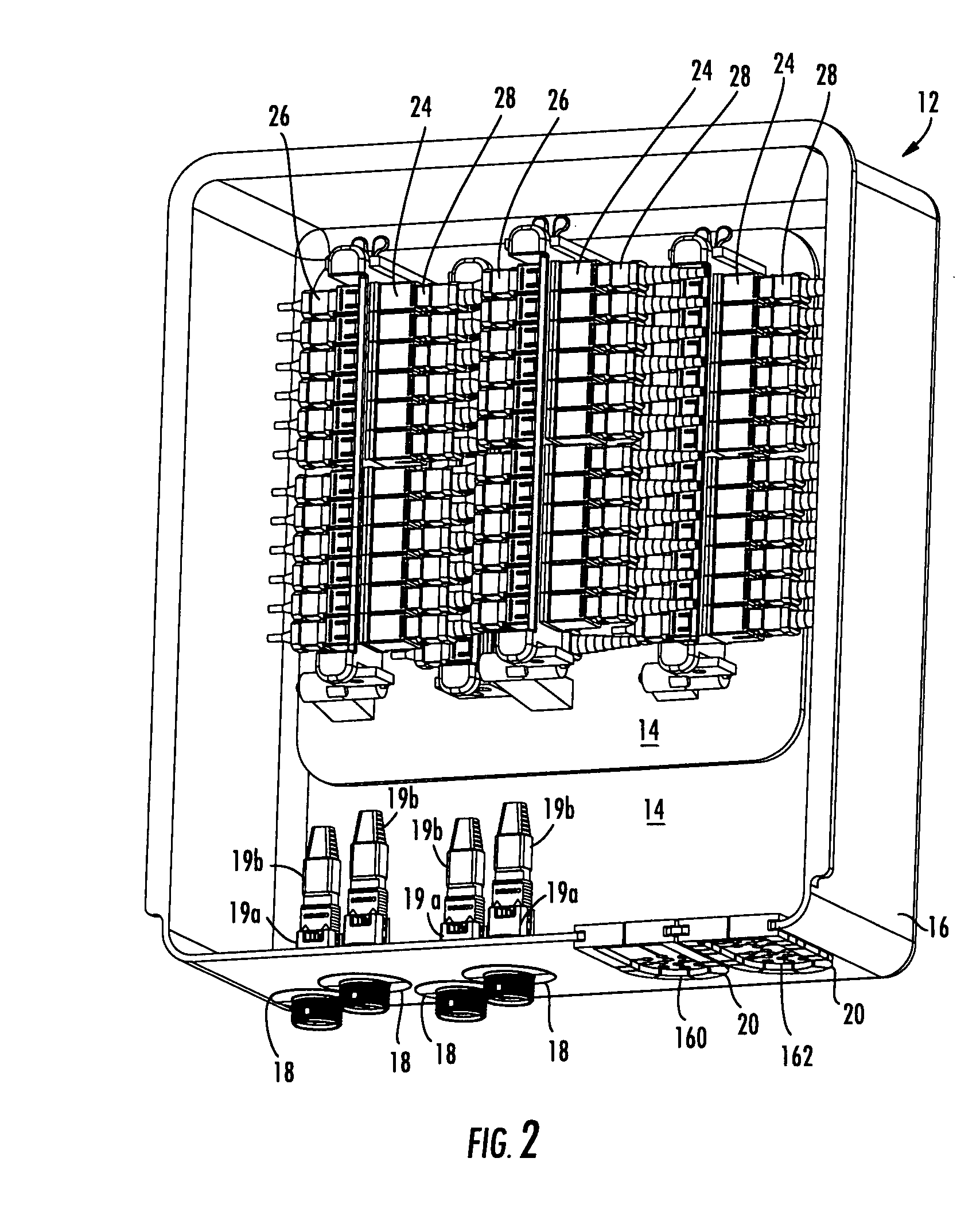
[0008]The various embodiments of the present invention address the above needs and achieve other advantages by providing fiber drop terminals (“FDTs”) that are adapted for use with microstructured optical fibers and / or other optical fibers that enable unique size, shapes, features, and other parameters. The FDTs of the present invention provide not only a small “footprint” (area / volume required for placement of the FDT), but the FDTs also provide for convenient and secure access to the optical connections within the FDT. Still further advantages will be appreciated by those skilled in the art.
[0010]Further embodiments of the present invention include FDTs with a distribution cover provided between the base and the cover. The distribution cover is adapted to provide limited access to the portion of the adapters that receive a connector of the distribution cable. Therefore, the service provider may prevent unauthorized access to the service provider side of the FDT. In addition, further embodiments comprise a removable and / or rotatable bracket for mounting the pluralities of adapters to thereby allow convenient handling of the pluralities of adapters within the FDT.
[0011]Still further embodiments of the present invention provide fiber optic hardware associated with FDTs and other fiber optic closures. Therefore, the FDTs and associated hardware of various embodiments of the present invention provide for convenient and secure optical connectivity while requiring relative smaller areas and volumes when compared to prior art closures.

Problems solved by technology

However, such FDTs are large and are generally not desirable for installation on each floor or other section of an MDU based upon the size of their footprint, visibility, and other considerations.
Such large FDTs are also relatively expensive to produce and are generally less convenient to transport, install, and service.

Method used


Image

  • Fiber optic drop terminals for multiple dwelling units
  • Fiber optic drop terminals for multiple dwelling units
  • Fiber optic drop terminals for multiple dwelling units

Examples


Embodiment Construction

[0049]The present invention now will be described more fully hereinafter with reference to the accompanying drawings, in which some, but not all embodiments of the invention are shown. Indeed, the invention may be embodied in many different forms and should not be construed as limited to the embodiments set forth herein; rather, these embodiments are provided so that this disclosure will satisfy applicable legal requirements. Although apparatus and methods for providing optical connectivity between optical fibers of distribution cables and drop cables are described and shown in the accompanying drawings with regard to specific types of fiber drop terminals, also known as fiber distribution terminals, (collectively, “FDTs”), it is envisioned that the functionality of the various apparatus and methods may be applied to any now known or hereafter devised enclosures and related fiber optic network equipment in which it is desired to provide optical connections between optical fibers of ...


PUM


Abstract

There is provided fiber drop terminals (“FDTs”) and related equipment for providing selective connections between optical fibers of distribution cables and optical fibers of drop cables, such as in multiple dwelling units. The FDTs require relatively little area and / or volume while providing convenient connectivity for a relatively large number of optical connections. The FDTs include adapters for optically connecting the connectors, and the adapters of some FDTs are adapted to rotate, move, or otherwise be removed to provide convenient access for technicians. Some FDTs and the related equipment are adapted for use with microstructured optical fiber having preferred bend characteristics.

Description

BACKGROUND OF THE INVENTION[0001]1. Field of the Invention[0002]The present invention is related to fiber drop terminals, and more particularly, to fiber drop terminals defining novel sizes, shapes, and / or functionality.[0003]2. Description of Related Art[0004]To provide improved performance to subscribers, fiber optic networks are increasingly providing optical fiber connectivity directly to the subscribers. As part of various fiber-to-the-premises (FTTP), fiber-to-the-home (FTTH), and other initiatives (generally described as FTTx), such fiber optic networks are providing the optical signals from distribution cables through local convergence points (“LCPs”) to fiber optic cables, such as drop cables, that are run directly or indirectly to the subscribers' premises. Such optical connectivity is increasingly being provided to multiple dwelling units (“MDUs”) in part because of the relatively large density of subscribers located in an MDU.[0005]MDUs include apartments, condominiums, ...

Claims


Application Information

Patent Timeline
Patent Type & Authority Applications(United States)
IPC IPC(8): G02B6/38G02B6/00
CPCG02B6/3897G02B6/4442H04Q1/023H04Q1/028H04Q1/021G02B6/4452G02B6/44524G02B6/44528
Inventor CASTONGUAY, GUYCLAPP, DONNIE RAYCOX, TERRY DEANLIGGETT, THOMAS SHAWPREVRATIL, KARYNE POISSANTRODRIGUEZ, DIANA
Owner CORNING OPTICAL COMM LLC
Learn More