
Method for generation of temporally high-resolution mr exposures

a high-resolution, exposure technology, applied in the field of generating high-resolution mr exposures, can solve the problems of complex method according to the prior, simplified image calculation, and complicated back-calculation of projections

Inactive Publication Date: 2008-08-28
SIEMENS HEALTHCARE GMBH
View PDF8 Cites 10 Cited by
  • Summary
  • Abstract
  • Description
  • Claims
  • Application Information

AI Technical Summary

Benefits of technology

[0007]An object of the present invention is to provide a method for generation of high-resolution MR exposures that likewise enables temporally high-resolution MR exposures with acceptable spatial resolution, which is simple and usable for many acquisition techniques.
[0013]Furthermore, the density compensation and conversion into a Cartesian coordinate system advantageously ensues in k-space so that a more homogeneous Cartesian raw data set exists to which fast Fourier transformation algorithms can be applied. This significantly accelerates the calculation of the MR image data and shortens overall the computation times for calculation of the MR images.
[0016]The density compensation function should compensate the acquisition with non-constant density in k-space, such that the density compensation function is advantageously selected in inverse proportion to the density of the sampling of k-space. If the density compensation function is not limited given large k-values (i.e. if high k-values, thus high signal frequencies, are suppressed in the image), the band artifacts in the image can likewise be suppressed. The limitation of the density compensation function at high k-values corresponds to a low-pass frequency filter that is applied to the image. This leads to two effects: first, the low-pass filtering expands the central portion of the density compensation function, thus leads to a signal smearing in the image. Second, it reduces the intensity of the band artifacts.
[0018]Overall the density compensation function should at most be so strongly attenuated that the central portion of the point spread function is narrower than half of the interval of the vessels to be compared. In all cases, however, the density compensation function must be attenuated so far for large k-values that the band artifacts are sufficiently suppressed that that signal dynamics lying spatially far apart are not mixed. Depending on the geometry to be presented, the density compensation function can now be set such that either the image sharpness increases (meaning as good as if no density compensation were implemented, but this increases the band artifacts), or the band artifacts are more strongly suppressed, which leads to a stronger signal smearing in the image.
[0019]A smearing in the under-sampled MR images does not lead to an image smearing in the vessels in the MR exposures but rather leads to a smearing of the dynamic information in the MR exposures that were generated via multiplication of the under-sampled MR images with the averaged MR image. The smearing in the under-sampled MR images leads to a dispersion (spreading) of the dynamic information.

Problems solved by technology

The complexity of the method according to the prior art is primarily due to the fact that this is the idea that the individual temporally high-resolution MR images representing a dynamic weighting coefficient of the individual images.
Furthermore, the inventive method foregoes the aforementioned calculation of the back-projections of the data, so the image calculation is simplified since the back-calculation of the projections is mathematically very complicated.
For arteries and veins lying close to one another it can naturally be helpful to suppress the veins in the reference image, by reconstructing the reference image only from a limited number of under-sampled MR raw data sets, although this naturally negatively affects the image quality.

Method used


Image

  • Method for generation of temporally high-resolution mr exposures
  • Method for generation of temporally high-resolution mr exposures
  • Method for generation of temporally high-resolution mr exposures

Examples


Embodiment Construction

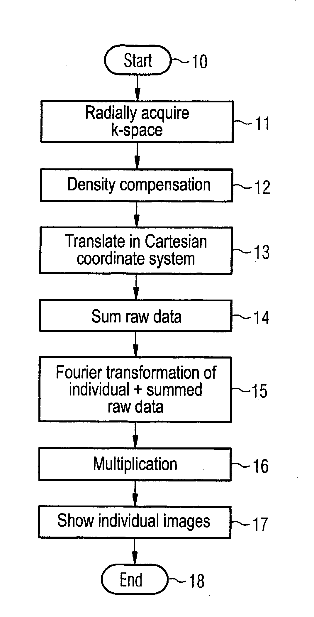
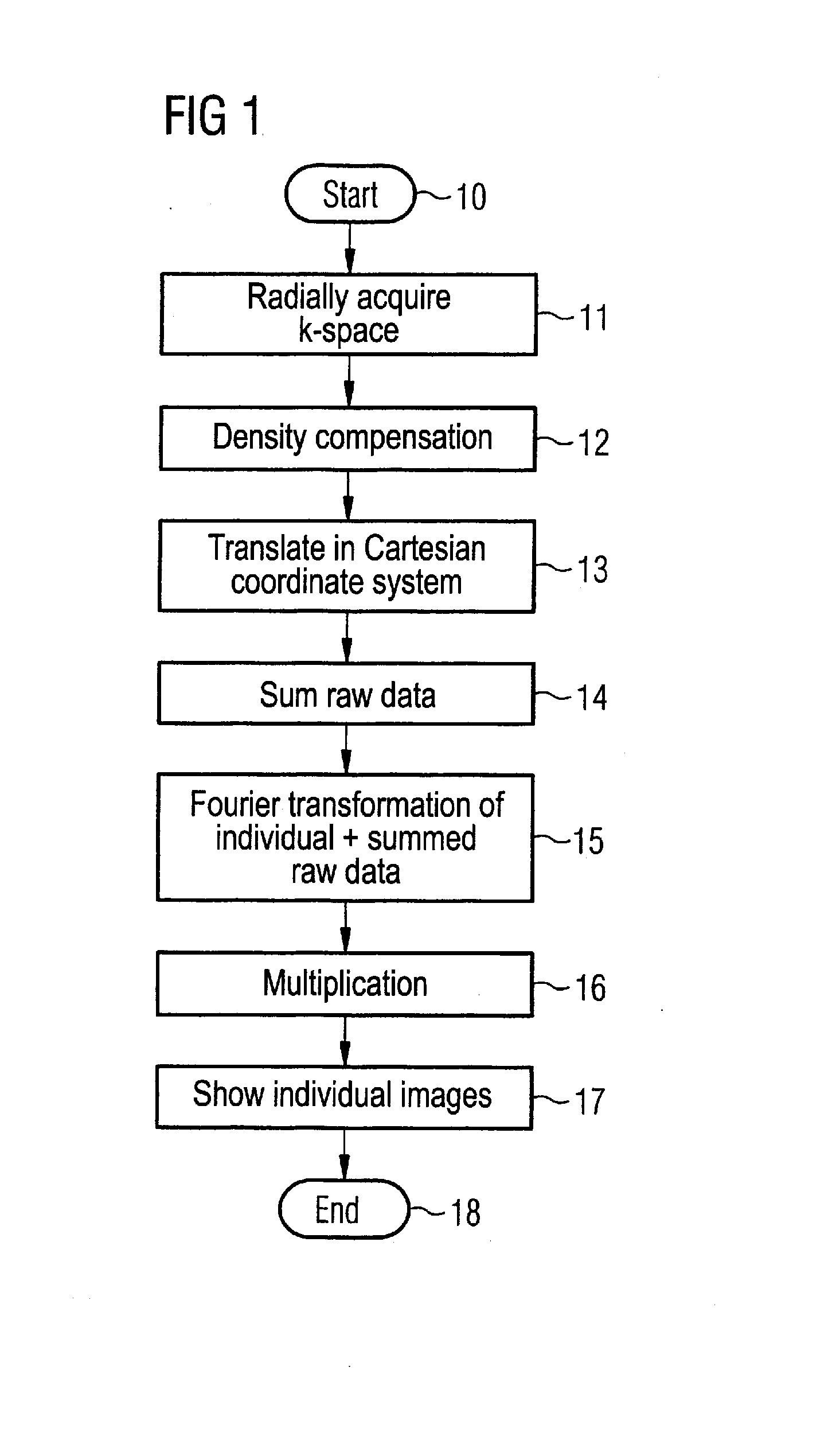
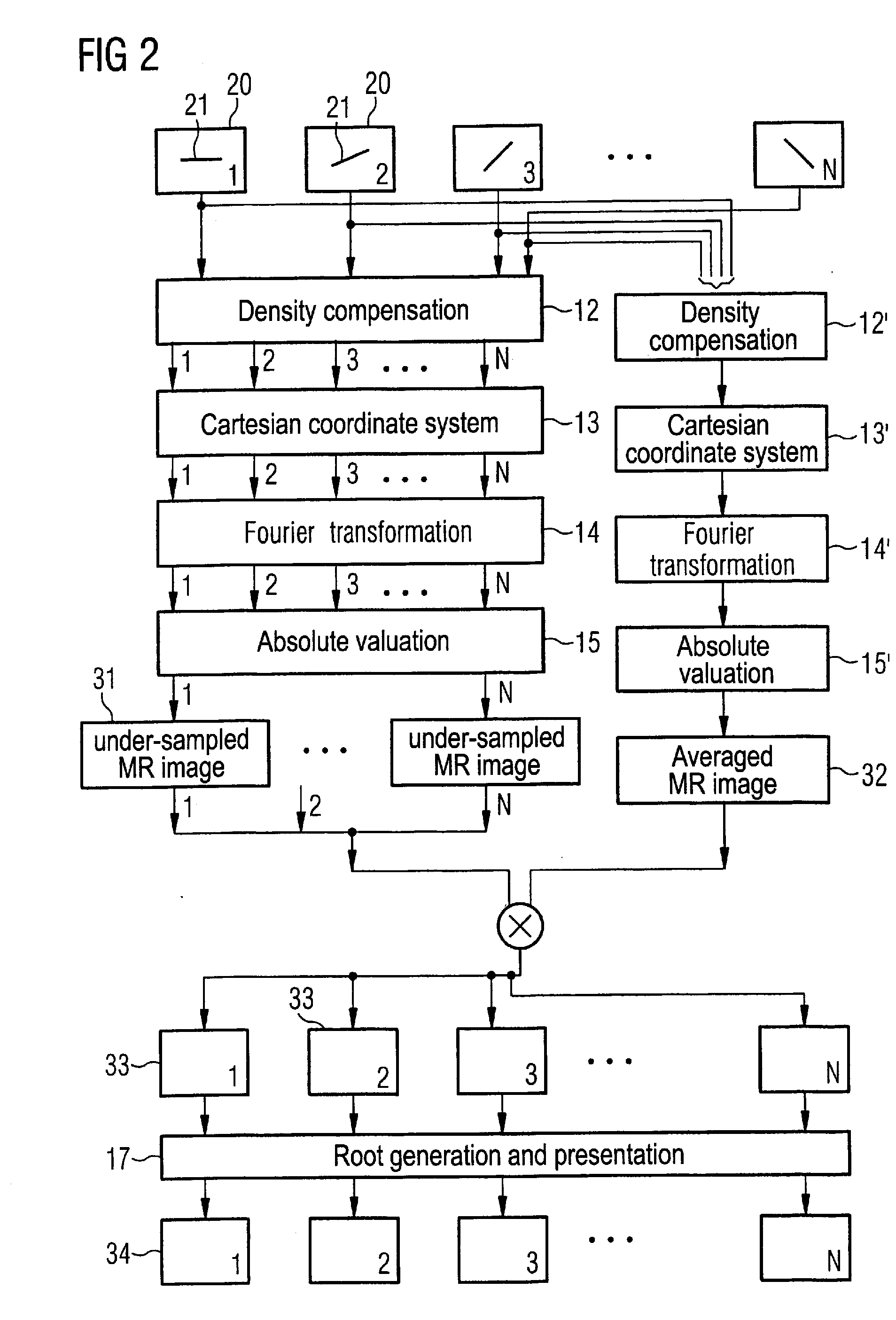
[0024]The inventive method is initially described on the basis of FIGS. 1 and 2. The method starts in a step 10. In a step 11 k-space or raw data space is filled with data with a radial acquisition technique, with a non-constant density of acquired k-space resulting from the radial acquisition technique. As shown in FIG. 2, in total N different under-sampled raw data are acquired. In the depiction selected in FIG. 2, each raw data set 20 exhibits a different trajectory 21, indicating that different projections are acquired for the various raw data. The two-dimensional, radially symmetrical exposure of k-space with various projections is shown as an example in FIG. 3. In this radially symmetrical exposure a measurement value is acquired at equidistant intervals along a projection 21 through the k-space center, with multiple projections 21 being used for each raw data set (for example a star as shown in FIG. 3). Different projections 21 are used for the various raw data sets 20 from F...


PUM


Abstract

In a method for generation of MR exposures in an MR system, a number of under-sampled MR raw data sets are acquired with non-constant density in k-space. A density compensation is implemented dependent on the geometry of the structure to be depicted. The under-sampled MR raw data sets are translated into a Cartesian coordinate system. Fourier transformation of the translated raw data sets in classical three-dimensional space ensues to generate under-sampled MR images. An averaged MR image is generated on the basis of a number of the under-sampled MR raw data sets. The MR exposures are produced by multiplication of the under-sampled MR images with the averaged MR image.

Description

BACKGROUND OF THE INVENTION[0001]1. Field of the Invention[0002]The present invention concerns a method for generation of temporally high-resolution MR exposures in a magnetic resonance system. The present application can in particular (but not exclusively) be used for generation of angiographic exposures by nuclear magnetic resonance.[0003]2. Description of the Prior Art[0004]In most MR applications it is desirable to obtain a high spatial resolution in the acquired MR images without extending the acquisition time too much. However, if the MR raw data set is acquired while adhering to the Nyquist condition (which means that the sampling rate is twice as high as the limit frequency to be depicted), the acquisition time automatically extends with increased spatial resolution since more raw data points must be collected in k-space.[0005]In addition to the typical MR acquisition techniques, radially symmetrical k-space data acquisition techniques have also been used in order to acceler...

Claims


Application Information

Patent Timeline
IPC IPC(8): G06K9/00
CPCA61B5/02007A61B5/055A61B5/7257G01R33/56509G01R33/561G01R33/563G01R33/5635G01R33/4824
Inventor NIELLES-VALLESPIN, SONIASCHMITT, PETERSPEIER, PETER
Owner SIEMENS HEALTHCARE GMBH
Learn More