
Hot water and heating system operating on the basis of renewable energy carriers

a renewable energy and hot water technology, applied in the field of hot water and heating systems, can solve the problems of substantial energy supply interruption, and achieve the effect of easy adjustment/control

Inactive Publication Date: 2008-08-28
KIOTO CLEAR ENERGY
View PDF54 Cites 17 Cited by
  • Summary
  • Abstract
  • Description
  • Claims
  • Application Information

AI Technical Summary

Benefits of technology

[0014]A SHE can also be a heat exchanger that facilitates a heat transfer from the brine to water.

Problems solved by technology

The continuous provision of energy poses a substantial problem in this context.

Method used


Image

  • Hot water and heating system operating on the basis of renewable energy carriers
  • Hot water and heating system operating on the basis of renewable energy carriers
  • Hot water and heating system operating on the basis of renewable energy carriers

Examples


Embodiment Construction

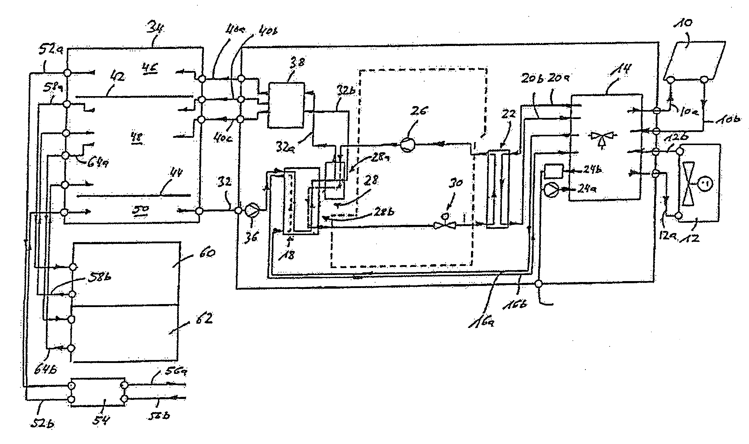
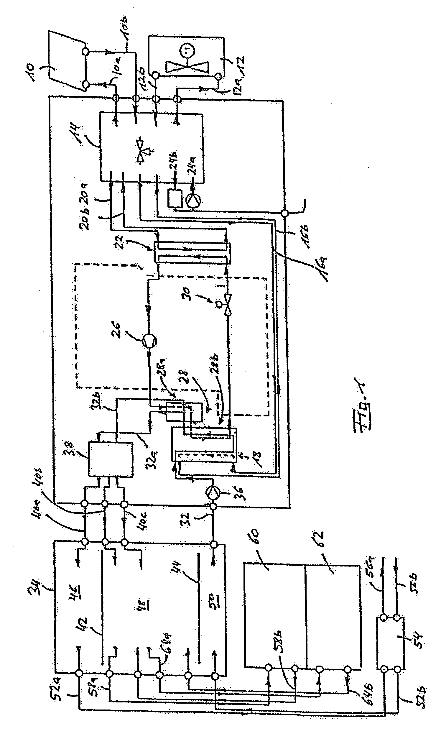
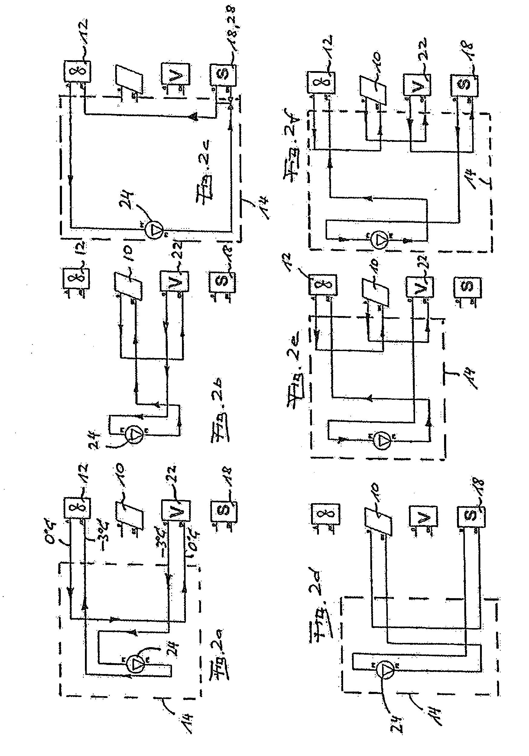
[0053]The reference sign 10 characterizes a group of solar collectors, and the reference sign 12a group of air heat exchangers. Glycol flows through both as a heat carrier medium, wherein supply and removal lines 10a, 10b for the solar collectors 10 and 12a, 12b for the air heat exchangers 12 are connected to a multiway valve 14.

[0054]From the multiway valve 14a line 16a runs to a plate heat exchanger 18; the corresponding return line is identified as 16b. Furthermore, a line 20a runs from the multiway valve 14 to a plate heat exchanger 22. The corresponding return line 20b discharges into the valve 14.

[0055]Also connected to the multiway valve 14 are a pressure and a suction side 24a, 24b of a pump, in order to be able to pump the glycol flow through the lines 10a, 10b, 12a, 12b, 16a, 16b, 20a, 20b, which together form the glycol circuit (=brine circuit).

[0056]The plate heat exchanger 22 is part of a heat pump, the related compressor of which is designated 26, the two-stage condens...


PUM


Abstract

The invention relates to a hot water and heating system, which operates on the basis of renewable energy carriers.

Description

FIELD OF THE INVENTION[0001]The invention relates to a hot water and heating system, which operates on the basis of renewable energy carriers.BACKGROUND OF THE INVENTION[0002]For economic and political reasons, the importance of renewable energies is becoming ever greater. Obtaining energy from the sun, air or geothermal heat is known in various embodiments. This also applies to combinations of the systems with one another.[0003]In the field of housing construction, but also in the case of offices or commercial buildings, it is particularly important to produce hot water for heating circuits and / or for heating fresh water.[0004]The continuous provision of energy poses a substantial problem in this context. In summer, solar energy is available virtually limitlessly; but in summer the minimum requirement also exists for hot water for heating purposes and / or for heating fresh water.[0005]In transitional periods such as autumn, and in winter, this requirement increases. When the sky is ...

Claims


Application Information

Patent Timeline
Patent Type & Authority Applications(United States)
IPC IPC(8): F24D3/08F24V50/00
CPCF24D3/08F24D11/003F24D11/0221F24D19/1045F24D19/1078Y02B30/126F25B30/06F28D20/0039Y02B10/20Y02B10/40Y02B10/70F25B6/04
Inventor BERGER, ERWINEUSCH, INGRAMKREINER, THOMASSTRICKER, ERWINPAVICSICS, REINHARD
Owner KIOTO CLEAR ENERGY
Learn More