
Wet-type friction material and its manufacturing method

Active Publication Date: 2008-08-21
AISIN CHEM CO LTD
View PDF5 Cites 21 Cited by
  • Summary
  • Abstract
  • Description
  • Claims
  • Application Information

AI Technical Summary

Benefits of technology

[0030]If the superficial part of the friction material substrate is laser-carbonized by the above fixed thickness, the following effects are obtained. Specifically, the laser beam has a stable light intensity and a fine adjustment of the light intensity is easy. Therefore, the laser beam can evenly carbonize a desired thickness of a resin and fibers existing at the superficial part of the ring-shaped friction material substrate or the segment pieces. Then, it is possible to give advantageous effects that thep-V gradient property is improved by carbonizing the superficial part. If the thickness of the carbonized portion is less than 1 μm in from the surface, the effect to improve the p-V gradient property is scarcely obtained. To the contrary, if the thickness of the carbonized portion exceeds 15 μm from the surface, the carbonized layer at the superficial part is peeled off.
[0031]According to the third aspect of the invention, it is possible to produce the wet-type friction material of the first aspect of the invention. Moreover, it is possible to carry out a step for giving the taper on the surface of the friction material substrate such as the ring-shaped friction material substrate or the plurality of the segment pieces simultaneously with a step for compressing and securing the friction material substrate on the surface of the core metal. Therefore, there is no special step needed. In addition, since a size of the taper is very small (not more than 5 / 100 at an outermost peripheral edge at a largest), a density of the friction material substrate is never changed. Therefore, a normal type of the core metal of the flat ring shape can be used. Furthermore, it is possible to eliminate a conventional initial smoothing operation or abrading work or cutting work, so that the manufacturing steps can be reduced and the manufacturing time can be shortened very much.
[0032]As a result, the manufacturing method is able to reduce a number of manufacturing steps and shorten a manufacturing time to a large extent.
[0033]According to the fourth aspect of the invention, it is possible to produce the wet-type friction material of the second aspect of the invention. Moreover, it is possible to carry out a step for giving the taper on the surface of the friction material substrate such as the ring-shaped friction material substrate or the plurality of the segment pieces simultaneously with a step for compressing and securing the friction material substrate on the surface of the core metal. Therefore, there is no special step needed. In addition, since a size of the taper is very small (not more than 5 / 100 at an outermost peripheral edge at a largest), a density of the friction material substrate is never changed. Therefore, a normal type of the core metal of the flat ring shape can be used. Furthermore, it is possible to eliminate a conventional initial smoothing operation or abrading work or cutting work, so that the manufacturing steps can be reduced and the manufacturing time can be shortened very much.
[0034]As a result, the manufacturing method is able to reduce a number of manufacturing steps and shorten a manufacturing time to a large extent.

Problems solved by technology

Consequently, it takes much time to obtain a target frictional coefficient and leads to an increase of manufacturing steps and a delay in a production time.
As a result, it has been impossible conventionally to attain a reduction in manufacturing costs.
Moreover, another problem is caused that there is produced unnecessary grinding sludge or cutting chips in these grinding step or cutting step.
However, in the technique described in the fourth patent publication, a strength at the inner peripheral side in the radial direction of the wet-type frictional facing becomes too high, in case a taper is given such that the density at the outer peripheral side in the radial direction of the wet-type frictional facing becomes smaller than the other part.
Consequently, it becomes difficult to make an entire surface of the wet-type frictional facing closely contact with the facing frictional surface, even if a pressure rises at the side of the facing frictional surface to which the wet-type frictional facing is oppositely located.
Moreover, in case a taper is provided at the outer peripheral side in the radial direction of the fixing surface, there is a problem that the piston as a whole must be manufactured separately from normal pistons.

Method used


Image

  • Wet-type friction material and its manufacturing method
  • Wet-type friction material and its manufacturing method
  • Wet-type friction material and its manufacturing method

Examples


first embodiment

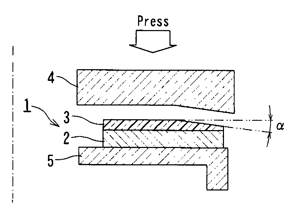
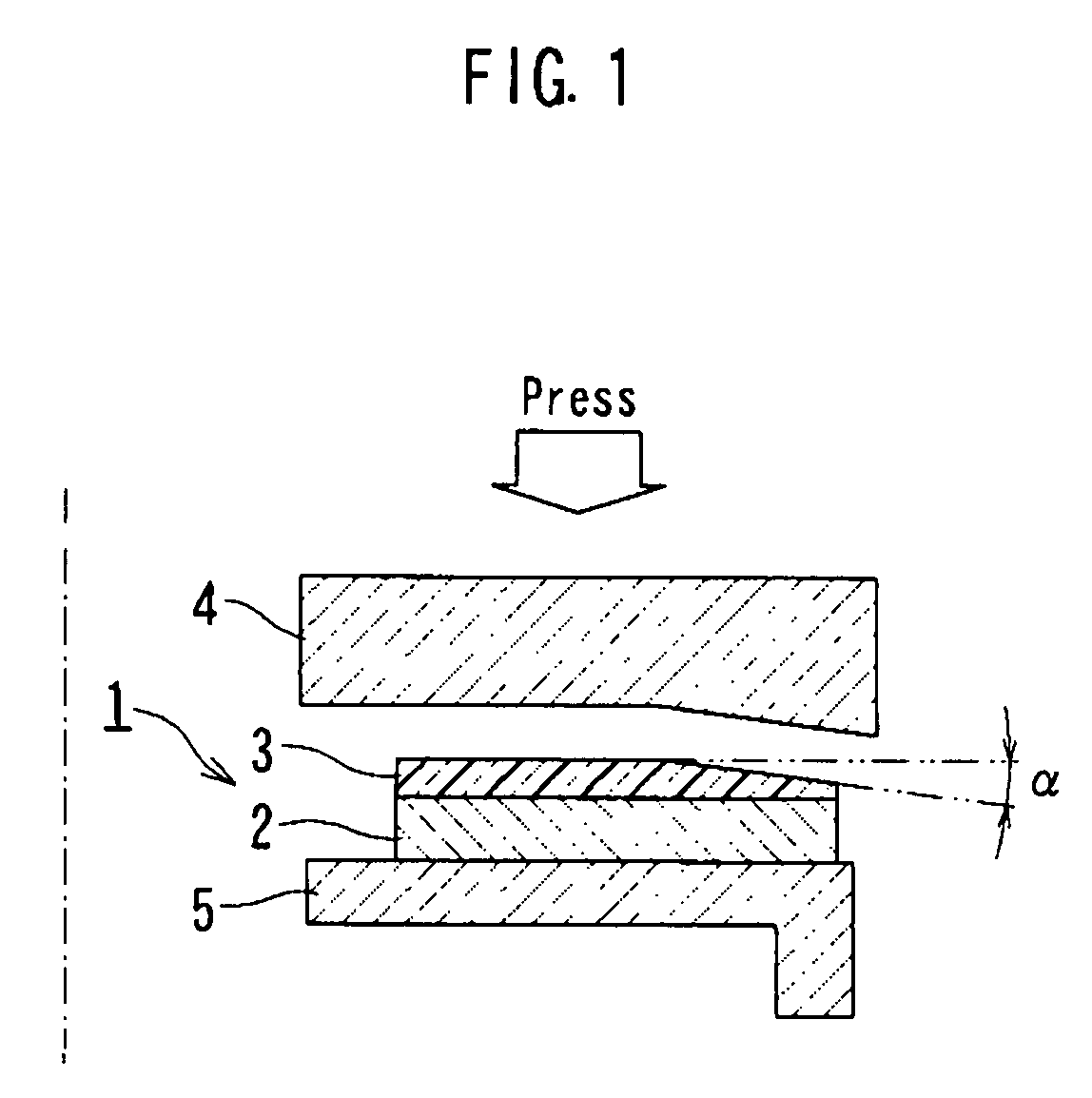
[0047]FIG. 1 is a cross-sectional view showing a schematic overall structure of a wet-type friction material and its manufacturing device according to a

[0048]As shown in the cross-sectional view of FIG. 1, a wet-type friction material 1 according to the first embodiment is a ring-shaped wet-type friction material 1. The ring-shaped wet-type friction material 1 has a core metal 2 of a flat ring plate shape and a ring-shaped friction material substrate 3 adhered and fixed on a surface of the core metal 2. The ring-shaped friction material substrate 3 is cut out of a friction material substrate in a shape of a strip sheet or the like as a raw material. The raw material strip sheet has a same or even thickness as a whole, and a blank of the friction material substrate 3 before processing has a fixed and constant thickness as a whole, though FIG. 1 shows a state of the friction material substrate 3 after the processing and the substrate 3 has an uneven thickness part.

[0049]A one-dot chai...

second embodiment

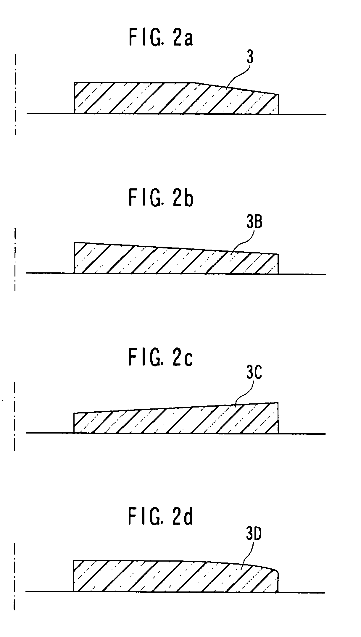
[0060]FIG. 2b is a cross-sectional view showing a sectional shape of a ring-shaped friction material substrate of a wet-type friction material according to the invention.

[0061]FIG. 2b illustrates a cross-sectional shape of a ring-shaped friction material substrate 3B according to the second embodiment. The friction material substrate 3B linearly changes a thickness in a radial direction from an inner peripheral edge to an outer peripheral edge along a full length thereof so as to form a tapered portion having a linearly inclined friction surface thereon. The tapered portion (i.e. entire friction material substrate 3B) is an outwardly tapered portion. An area of the tapered portion or a length of the inclined surface in the friction material substrate 3B becomes longer than the friction material substrate 3 of the first embodiment if their lengths of the substrates 3, 3B are the same. The friction material substrate 3B is cut out of the same raw material as the first embodiment of th...

third embodiment

[0062]FIG. 2C is a cross-sectional view showing a sectional shape of a ring-shaped friction material substrate of a wet-type friction material according to the invention.

[0063]FIG. 2C illustrates a cross-sectional shape of a ring-shaped friction material substrate 3C according to the third embodiment. The third embodiment of the friction material substrate 3C has such a line-symmetric shape to the second embodiment of the friction material substrate 3B. Specifically, the friction material substrate 3C linearly changes a thickness in a radial direction from an outer peripheral edge to an inner peripheral edge along a full length thereof so as to form a tapered portion having a linearly inclined friction surface thereon. The tapered portion (i.e. entire friction material substrate 3C) is an outwardly tapered portion in contrast with the friction material substrate 3B. The friction material substrate 3C is cut out of the same raw material as the first embodiment of the friction materia...


PUM


Abstract

In a wet-type friction material, a ring-shaped friction material substrate is compressed and fixed on a surface of a core metal by heat-pressing by a manufacturing metal mold. At the same time, a taper of an angle α corresponding to a taper at an outer peripheral side of an upper mold is provided on an outer peripheral side of the ring-shaped friction material substrate. Thus, the taper is formed such that a thickness in a radial direction of the ring-shaped friction material substrate becomes smaller from a middle point toward an outer peripheral edge.

Description

BACKGROUND OF THE INVENTION[0001]1. Field of the Invention[0002]This invention relates to a wet-type friction material and its manufacturing method that is able to stabilize an initial frictional property of the wet-type friction material without using a polishing device or a cutting device, thereby shortening a manufacturing time to a large extent, while preventing unnecessary polishing dusts or cutting dusts from being generated.[0003]2. Description of the Related Art[0004]Commonly used wet-type friction material for an automatic transmission is composed of a core metal of a flat ring plate shape and a friction material substrate. The friction material substrate is made of a ring-shaped friction material substrate sheet (may be referred to as “ring sheet” hereafter) or a plurality of segmented friction material sheets (may be referred to as “segment pieces” hereafter). Either of the ring sheet and the segment pieces is cut out from a friction material substrate as a base material ...

Claims


Application Information

Patent Timeline
IPC IPC(8): B32B1/00B32B37/10
CPCF16D13/64F16D69/02F16D2069/005F16D2069/0483Y10T428/13F16D2250/00Y10T428/21Y10T428/218Y10T428/213F16D2069/0491
Inventor HASEGAWA, MASATOOKAMURA, HIROKI
Owner AISIN CHEM CO LTD
Learn More