
Power generating systems and methods

a power generation system and power technology, applied in the direction of electric generator control, wind motor with solar radiation, greenhouse gas reduction, etc., can solve the problems of poor thermal efficiency of state-of-the-art engines and thermal power generating plants, adversely changing the climate of the planet, etc., to promote the reduction of greenhouse gas production

Inactive Publication Date: 2008-08-21
PRIMLANI INDRU J
View PDF32 Cites 18 Cited by
  • Summary
  • Abstract
  • Description
  • Claims
  • Application Information

AI Technical Summary

Benefits of technology

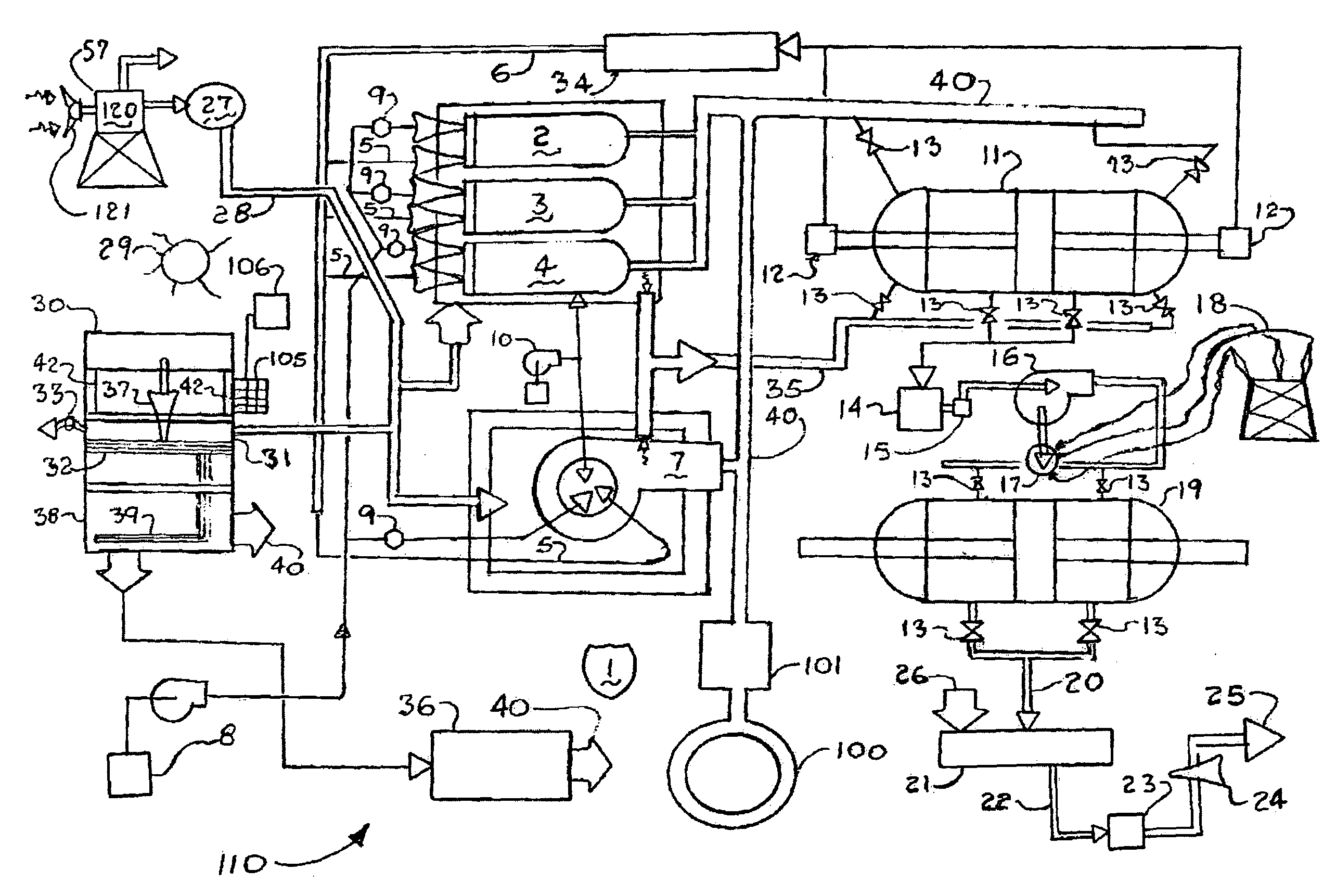
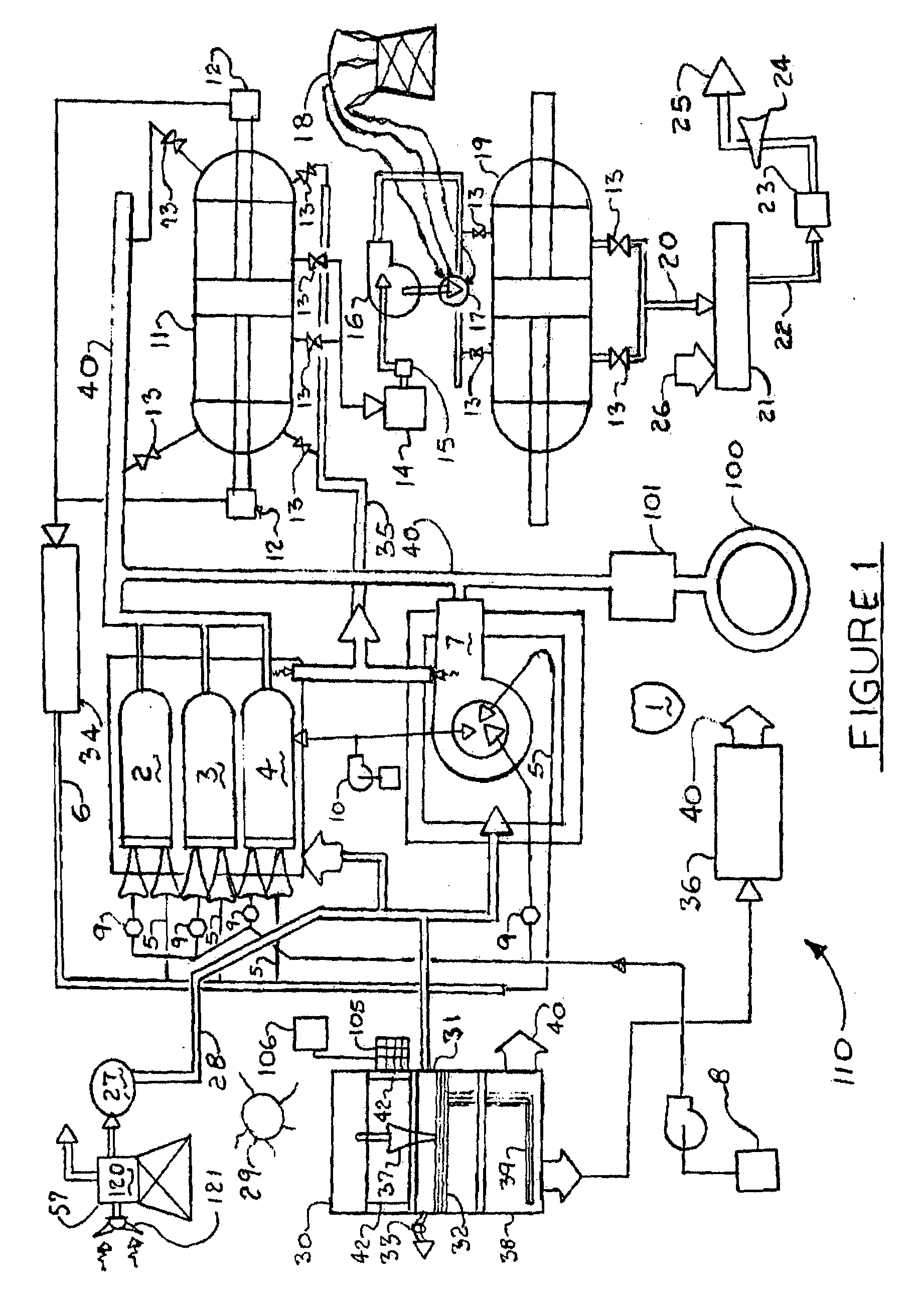
[0013]According to yet another embodiment, a method of minimizing emission of greenhouse gases from an exhaust fluid of a power-generating system and slowing global warming, comprises reacting at least a portion of the exhaust fluid including carbon dioxide and sulfur dioxide with an alkaline reagent to produce a solid particulate, and separating and disposing of the solid particulate, thereby reducing the emissions of greenhouse gases including carbon dioxide from the exhaust fluid.
[0014]According to still another embodiment, a system for minimizing greenhouse gases from an exhaust fluid of a power-producing system and slowing global warming, comprises a reaction chamber configured to receive at least a portion of the exhaust fluid, and a mixing device configured to mix a liquid and an alkaline reagent to form an atomized solution, the mixing device being in fluid communication with the reaction chamber to supply the atomized solution thereto, the reaction chamber reacting the exhaust fluid and the atomized solution for reducing greenhouse gases including carbon dioxide.

Problems solved by technology

Scientists are certain that human activities are changing the composition of the atmosphere, and that increasing the concentration of greenhouse gases will adversely change the planet's climate.
However, they are not sure by how much it will change, at what rate it will change, or what the exact effects will be.
State of the art engines and thermal power generating plants generally have poor thermal efficiencies, for example, in the range of 30 to 40%.
This is due to heat lost by system cooling, friction of moving parts and energy lost in exhaust gases.
Such inefficiencies typically produce large amounts of carbon dioxide that are spewed into the atmosphere.

Method used


Image

  • Power generating systems and methods
  • Power generating systems and methods
  • Power generating systems and methods

Examples


example i

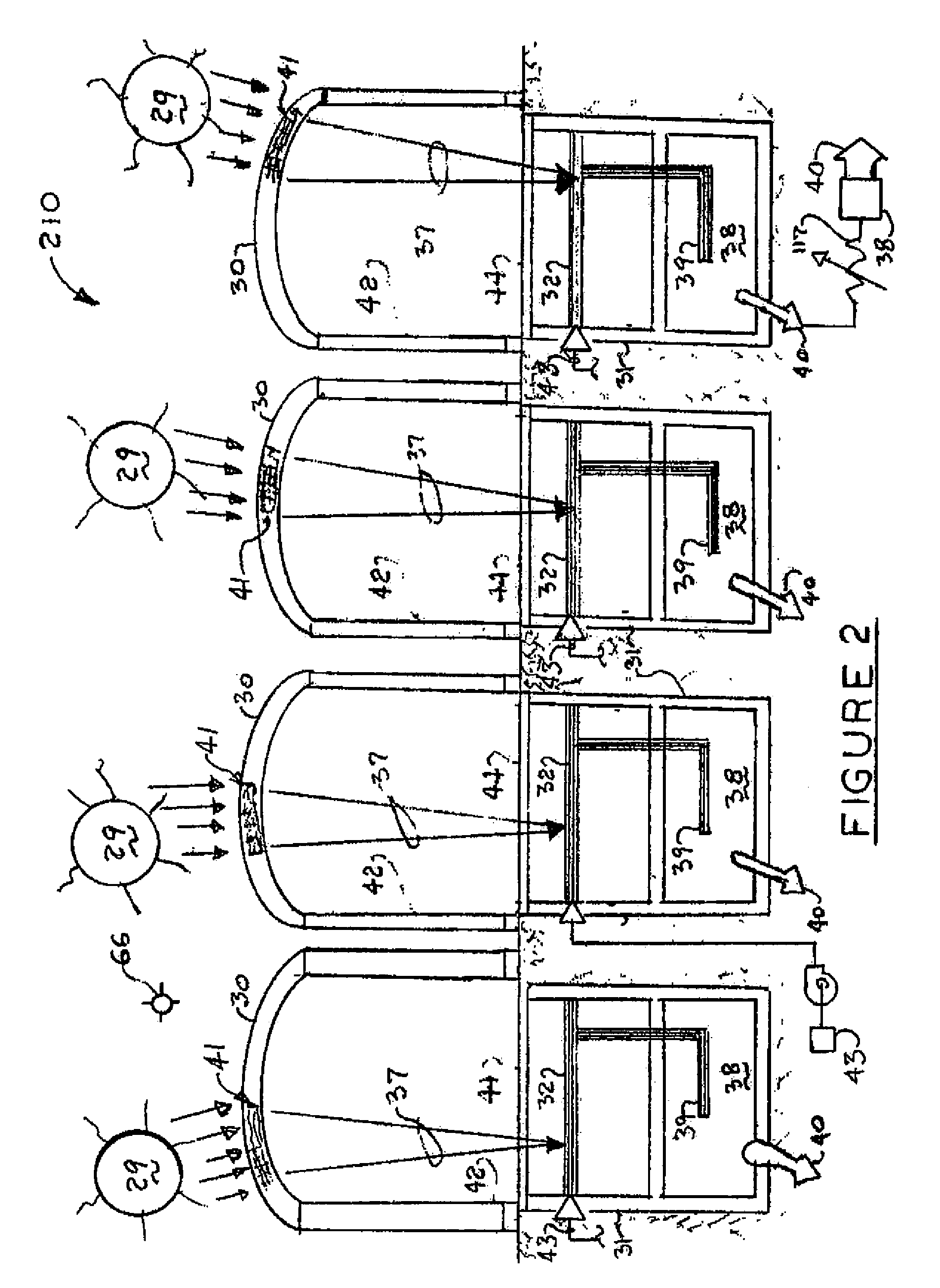
[0040]As one example of an application of a power-generating system according to one embodiment, FIG. 4 illustrates a stand alone, off the grid, solar house 410. Typically the sun 29 can provide at least 100 watts of solar power per square foot. If under-ground water is available, substantially no utility service will be required. Otherwise the only utility service added for the solar house 410 may be for water. During initial stages of such a system, a standby thermal power system using a suitable fossil fuel can be used as a backup system. Experience and additional storage of energy may lead to a solar house without any backup fuel system.

[0041]The solar house 410 can be any building, such as a personal residence, an office, a clinic or a building for commercial use. As illustrated in FIG. 4, the solar house 410 includes a roof section 48 having an extended overhang so as to shade some or all fenestration or openings, which can be positioned at a suitable angle such that the roof ...

example ii

[0047]A power-generating system according to an embodiment of the present disclosure makes it feasible to capture, store and utilize solar energy in self-propelled vehicles. This feature is particularly useful in zones of high solar energy in areas with minimum cloud cover and shadows. There are numerous opportunities to take advantage of these features for operating aircraft, ships, railroad trains and truck trains.

[0048]In some embodiments, solar collectors mounted on a towable structure can be stationed on standby to pickup solar energy until it is ready to be hitched to the vehicle. An umbilical cord structurally suitable for towing can include conduits for delivering the primary fluid or working fluid along with controls and electrical power connections.

[0049]This new technology includes storing large volumes of high-pressure fluids, such as gases, developed by concentrated solar rays when parked and made ready for a long journey. The fluid pressure can increased by thermal com...

example iii

[0053]As another example of an application of a power-generating system according to one embodiment, FIG. 6 illustrates a solar powered aircraft 60. Extraterrestrial solar energy incident outside an atmosphere of earth is about 1,370 watts per square meter and varies about ±3% depending on a position of earth in an orbit of the sun. The solar energy incident upon a surface of earth is typically about 40% less than that at high altitudes, such as 30,000 feet above sea level. This implies that more solar energy is available at high altitudes that can provide for powering airborne vehicles such as the solar powered aircrafts 60. Further, cloud cover is minimal at high altitudes and typically there are no shadows. While the shadow of the earth shields the solar rays at night, polar flights can reduce the nighttime shadow. Accordingly, large number of inter-continental flights can be routed over polar areas.

[0054]There is an inexhaustible source of solar energy available at these lofty a...


PUM


Abstract

A power-generating system is provided for operating adiabatically and reducing emissions of greenhouse gases contributing to global warming. The system may include gas reactors and / or combustors that burn a fuel and an oxygen-containing gas under substantially adiabatic conditions such that high-pressure combustion products and low pressure combustor housing cooling air are combined to produce a medium pressure working fluid. Higher thermal efficiencies reduce emissions of greenhouse gases. Products of combustion can be processed to further reduce emissions of carbon dioxide and other greenhouse gases from portable and stationary exhaust-producing devices using different fuels. The system may also include solar collectors that pick up a spectrum of solar energy by means of cells containing fluids, aligned to concentrate the solar rays. The collectors may pick up direct and / or diffused solar radiation and can be used to power self-propelled vehicles or function as a roof of a building.

Description

CROSS-REFERENCE TO RELATED APPLICATION[0001]This application is a continuation-in-part of U.S. patent application Ser. No. 11 / 534,876, filed Sep. 25, 2006, now pending, which application is a divisional of U.S. patent application Ser. No. 11 / 105,130, which application issued as U.S. Pat. No. 7,134,285 and is a continuation-in-part of U.S. patent application Ser. No. 10 / 733,898, which application issued as U.S. Pat. No. 6,955,052, where these (three) documents are incorporated herein by reference in their entirety.BACKGROUND[0002]1. Technical Field[0003]The present invention generally relates to power generating systems, and more particularly, to systems and methods for generating power adiabatically and via solar energy.[0004]2. Description of the Related Art[0005]For over the past 200 years, the burning of fossil fuels, such as coal and oil, and deforestation have caused the concentrations of heat-trapping “greenhouse gases” to increase significantly in our atmosphere. These gases ...

Claims


Application Information

Patent Timeline
IPC IPC(8): F03G6/02F03G6/06F02C6/04F03D9/02
CPCF02C1/05F03D9/007F03D9/02F03G6/02F03G6/065Y02E10/72Y02B10/20Y02B10/30Y02B10/70Y02E10/465F05D2220/75F03D9/10F03D9/17F03D9/28H02S10/12Y02B10/10Y02E10/46Y02E10/50Y02E60/16Y02E70/30
Inventor PRIMLANI, INDRU J.
Owner PRIMLANI INDRU J
Learn More