
Engineering System

Inactive Publication Date: 2008-08-14
SIEMENS AG
View PDF11 Cites 11 Cited by
  • Summary
  • Abstract
  • Description
  • Claims
  • Application Information

AI Technical Summary

Benefits of technology

[0010]In a further development of the invention, at least one component of the automation mechanism is provided with means of transferring maintenance-relevant information to the engineering system. This maintenance-relevant data can include, for example, the operating time of a component, the over- or undershooting of a threshold value or specific information concerning maintenance. It is also provided that a data record containing maintenance-relevant information is stored in individual components of the automation mechanism. This has the advantage that, after the installation of new components, their maintenance-relevant data does not need to be entered in the system, but can be transferred automatically. Subsequent revision of the maintenance-relevant information is also possible.
[0024]In a preferred embodiment of the invention, maintenance-relevant information is stored on a server and retrieved via at least one client. It is provided to store the maintenance-relevant information centrally. To increase reliability, the server can be of redundant design. On clients, components combined into component groups in a hierarchically arranged manner can be selectively selected.

Problems solved by technology

The separate handling of the engineering and / or configuring of a project representing an automation mechanism of a plant to be controlled (technology view) on the one hand, and the engineering of diagnostic and maintenance actions on the other, is prone to error.

Method used


Image

  • Engineering System
  • Engineering System
  • Engineering System

Examples


Embodiment Construction

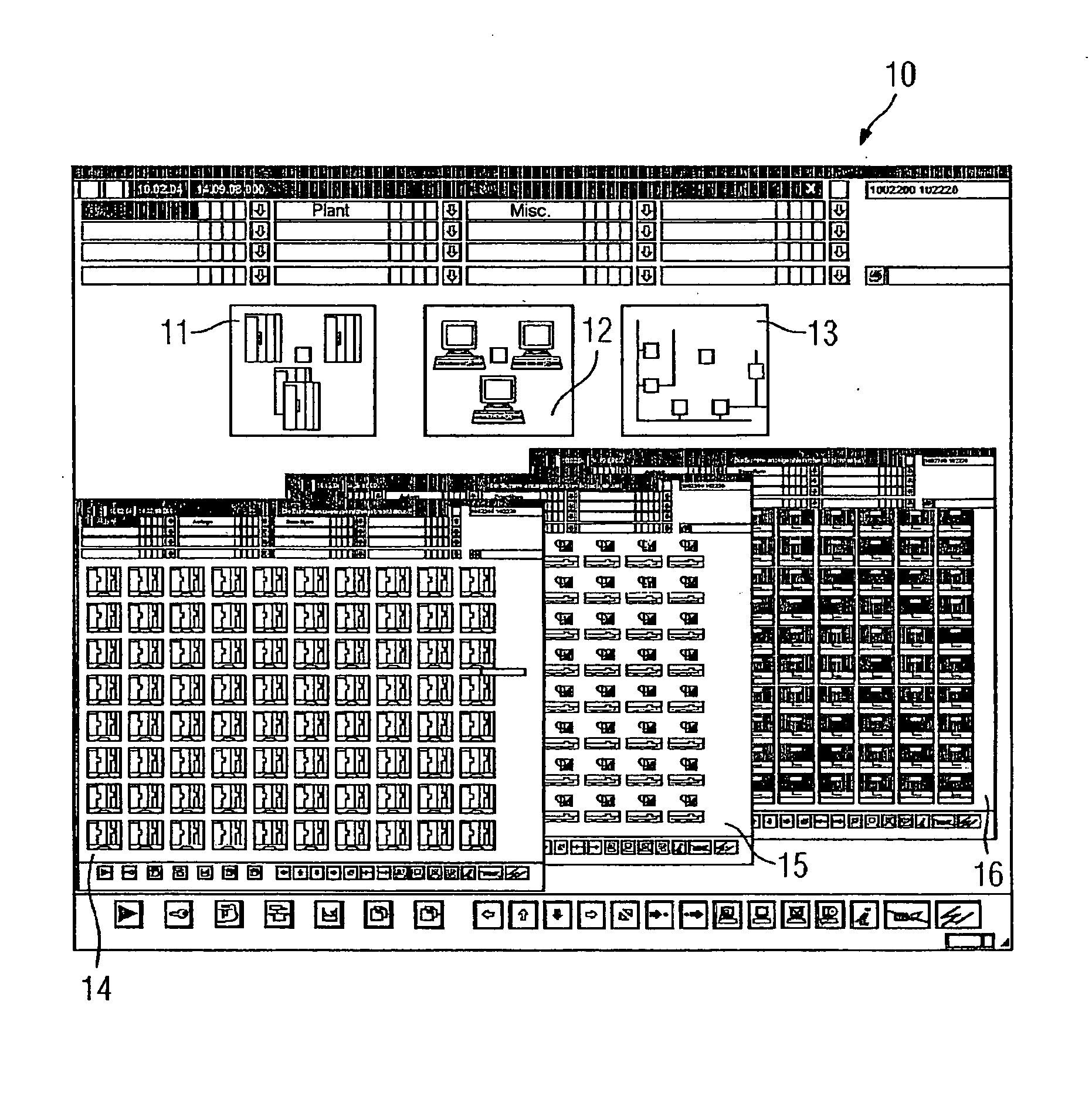
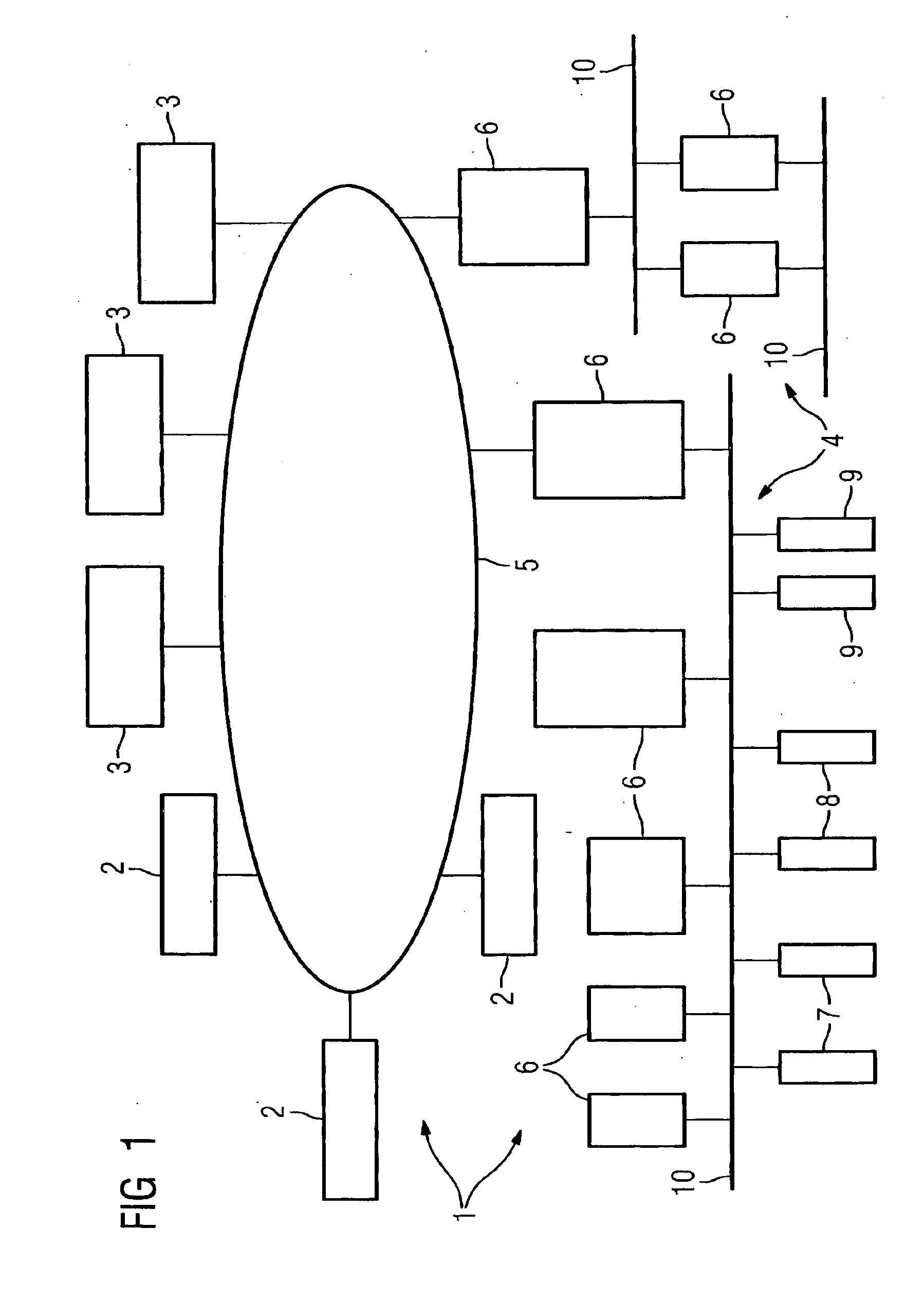
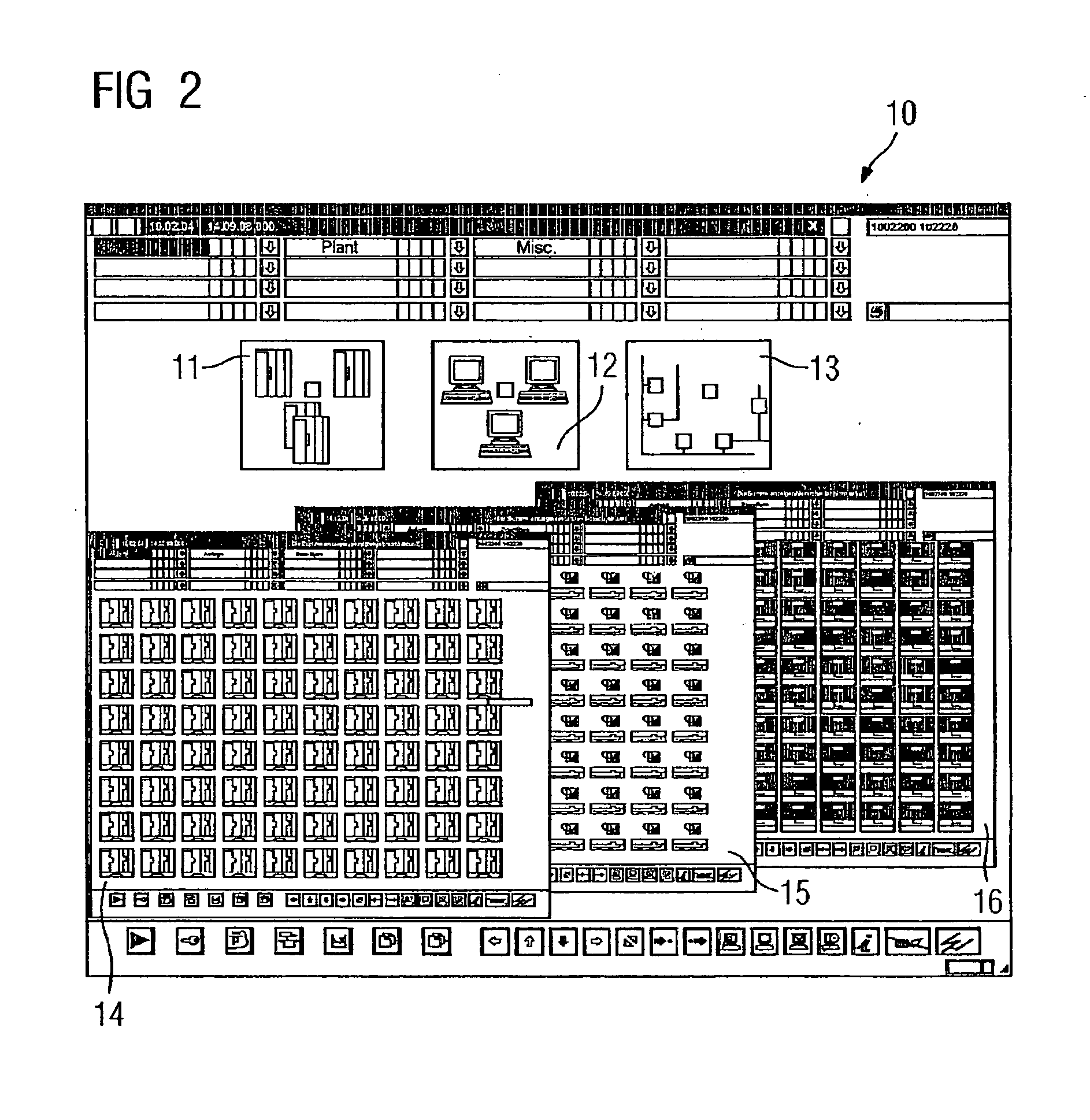
[0039]FIG. 1 shows a per se known process control system 1 comprising an engineering system 2, an operator control and monitoring system 3 and an engineered and configured automation mechanism 4, the engineering system 2 being designed for the engineering and / or configuring of the automation mechanism 4. The automation mechanism 4 which is connected to the engineering system 2 and the operator control and monitoring system 3 via a bus system 5 and bus connections (not shown) comprises different programmable controllers 6, plus actuators 7 and sensors 8 as well as other automation components 9 required for controlling an industrial plant. The programmable controllers 6, which are interconnected via the bus system 5 and / or other suitable bus systems 10, can be of different design. For example, programmable controllers for performing small, medium or larger automation tasks within the automation mechanism 4 are usually provided, micro-programmable controllers possibly being used to per...


PUM


Abstract

There is described an engineering system for an automation system having data required for engineering the automation system stored in the engineering system, and a determination device to determine automatically in response to a user request from the engineered automation system, maintenance-relevant information for display in a diagnostics area on a visualization system. Furthermore there is described a method for maintaining an automation system having components, wherein the components are connected to an engineering system and maintenance-relevant information is determined by the engineering system. The maintenance-relevant information can be displayed by the engineering system.

Description

CROSS REFERENCE TO RELATED APPLICATIONS[0001]This application is the US National Stage of International Application No. PCT / EP2006 / 060261, filed Feb. 24, 2006 and claims the benefit thereof. The International Application claims the benefits of German application No. 10 2005 009 380.9 DE filed Mar. 1, 2005, and German application No. 10 2005 028 488.4 DE filed Jun. 20, 2005, all of the applications are incorporated by reference herein in their entirety.FIELD OF INVENTION[0002]The invention relates to an engineering system for engineering and / or configuring a project representing an automation mechanism of a plant to be controlled, wherein the project data required for engineering and / or configuring the automation mechanism can be stored in the engineering system.BACKGROUND OF INVENTION[0003]An engineering system of this kind is known from the Siemens catalog ST PCS 7, Sections 1 and 4, 2004 edition. A process control system for controlling a plant incorporates an engineering system w...

Claims


Application Information

Patent Timeline
IPC IPC(8): G06F3/048G06Q10/00
CPCG06Q10/06G05B2219/31471
Inventor EISEN, WOLFGANGRACHUT, HOLGER
Owner SIEMENS AG
Learn More