Photoacoustic measuring device and method
- Summary
- Abstract
- Description
- Claims
- Application Information
AI Technical Summary
Benefits of technology
Problems solved by technology
Method used
Image
Examples
first embodiment
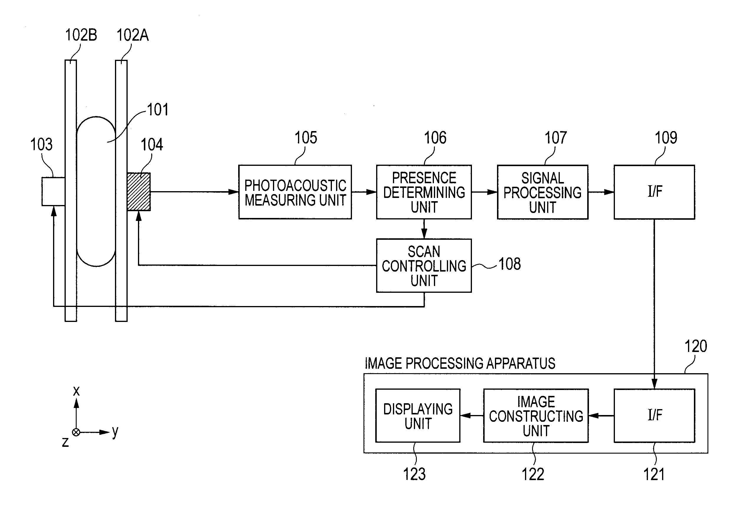
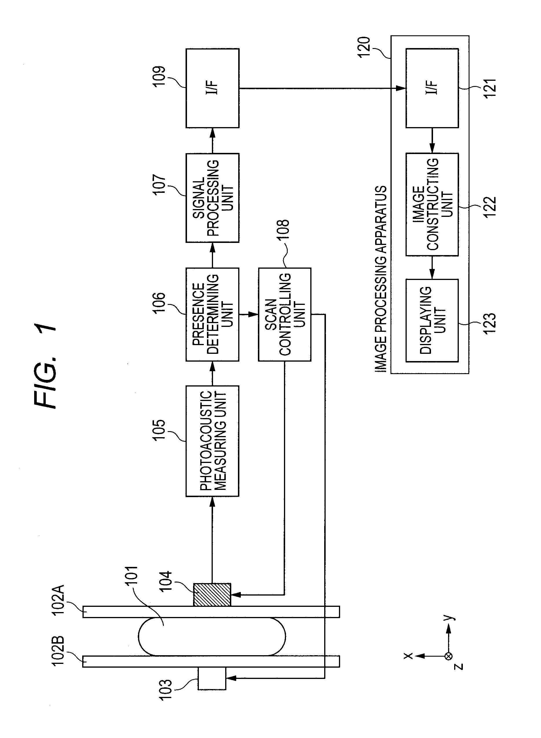
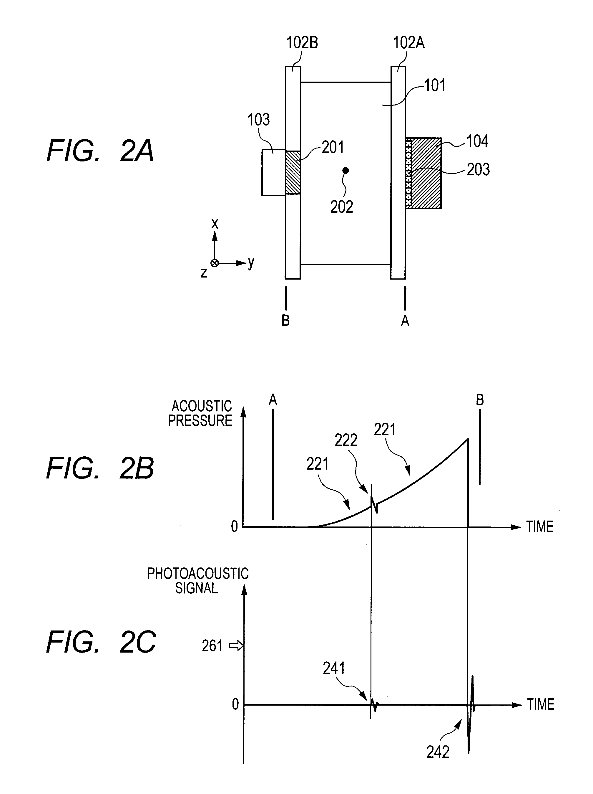
[0026]The first embodiment using a photoacoustic measuring device or method according to the present invention will be described with reference to the drawings. As illustrated in FIG. 1, a photoacoustic measuring system according to the first embodiment has a holding plate 102 which holds an object 101, an irradiating unit 103 which irradiates a measuring beam and a photoacoustic wave detecting unit 104 which includes acoustic wave detecting devices that form a detecting unit which detects a photoacoustic wave generated by irradiated light. Further, the photoacoustic measuring system has a photoacoustic measuring unit 105 which amplifies and converts a signal detected by the photoacoustic wave detecting unit 104 into a digital signal, a presence determining unit 106 which is a characteristic unit according to the present embodiment, and a signal processing unit 107 which performs, for example, recording processing of the detected photoacoustic signal. Further, the photoacoustic meas...
second embodiment
[0054]Next, a second embodiment for realizing the present invention will be described. According to the first embodiment, with a configuration where the light source and probe are arranged to oppose to each other across the object 101, and the probe is irradiated with the measuring beam 201 from the opposite side, the presence of the object 101 is identified. In contrast to this, features of the second embodiment include identifying the presence of an object similar to the first embodiment in a configuration where a light source and probe are arranged in the same direction and a measuring beam is irradiated from the same side, the side on which there is the probe. Further, by extracting a photoacoustic signal in the interface required to identify the presence of the object using signal characteristics of the photoacoustic signal, an accidental detection signal such as noise is removed. The second embodiment will be described mainly concerning the above features.
[0055]FIG. 6 is a sch...
third embodiment
[0076]The purpose of the present invention can also be achieved by the following embodiment. That is, a storage medium (or recording medium) which stores a program code of software for realizing the function (particularly, the function of the presence determining unit forming an analyzing unit or control unit) of the above embodiments, is supplied to a system or device. Then, a computer (or Central Processing Unit (CPU) or Micro Processing Unit (MPU)) of the system or device reads and executes a program code stored in the storage medium. In this case, the read program code from the storage medium itself realizes the function of the above embodiments, and the storage medium which stores this program code configures the present invention.
[0077]Further, by executing the program code read by the computer, the operating system (OS) operating on the computer performs a part or all of actual processings based on the command of this program code. A case where the function of the above embod...
PUM
 Abstract
Description
Claims
Application Information
 - R&D
- Intellectual Property
- Life Sciences
- Materials
- Tech Scout
- Unparalleled Data Quality
- Higher Quality Content
- 60% Fewer Hallucinations
Browse by: Latest US Patents, China's latest patents, Technical Efficacy Thesaurus, Application Domain, Technology Topic, Popular Technical Reports.
© 2025 PatSnap. All rights reserved.Legal|Privacy policy|Modern Slavery Act Transparency Statement|Sitemap|About US| Contact US: help@patsnap.com


