
Optical element having Anti-reflection coating

an optical element and anti-reflection technology, applied in the field of optical elements having anti-reflection coatings, can solve the problems of reducing the anti-reflection coating. , to achieve the effect of excellent anti-reflection characteristics

Inactive Publication Date: 2008-08-14
HOYA CORP
View PDF6 Cites 16 Cited by
  • Summary
  • Abstract
  • Description
  • Claims
  • Application Information

AI Technical Summary

Benefits of technology

[0010]Accordingly, an object of the present invention is to provide a high-curvature optical element having excellent anti-reflection characteristics in an effective-diameter region to light in a wide wavelength range.

Problems solved by technology

However, there is no material having such an ideal refractive index.
However, the anti-reflection coating formed by these methods is generally thinner on a peripheral portion of the lens than on a center portion thereof.
Thus, the optical thickness is deviated from the designed thickness in a peripheral portion of the lens, and sufficient anti-reflection characteristics cannot be obtained because of a large incident angle as described above, resulting in an extremely large amount of reflected light.
Accordingly, such optical element suffers from the problem that although there is high transmission in a center portion, there is insufficient transmission in the entire element.
In addition, to form the anti-reflection coating by a vapor deposition method, a vacuum apparatus is needed, resulting in high production cost.
This optical element has high transmission as a whole, but the use of a conventional anti-reflection coating made of MgF2 having as relatively high a refractive index as 1.38 fails to provide satisfactory anti-reflection characteristics.
However, these methods are usable only on low-curvature lenses.
However, this porous anti-reflection coating has large hygroscopicity, resulting in water entering into fine pores during use to change the refractive index, etc.
Thus, it suffers from a serious problem of deterioration with time.
However, to provide the silica layer with sufficient hydrophobicity, heating should be conducted at higher than 400° C. Some molded glass lenses used as object lenses for light pickup apparatuses have glass transition temperatures lower than 400° C., and the method described in JP 2001-272506A cannot be applied to such lenses.
However, JP 2005-234447A and JP 2005-275372A disclose only optical lenses for spectacles, camera finder lenses, prisms, fly-eye lenses and toric lenses, but fail to describe the formation of anti-reflection coatings containing the above zinc compounds or alumina on high-curvature lenses such as object lenses for light pickup apparatuses, etc.

Method used


Image

  • Optical element having Anti-reflection coating
  • Optical element having Anti-reflection coating
  • Optical element having Anti-reflection coating

Examples


example 1

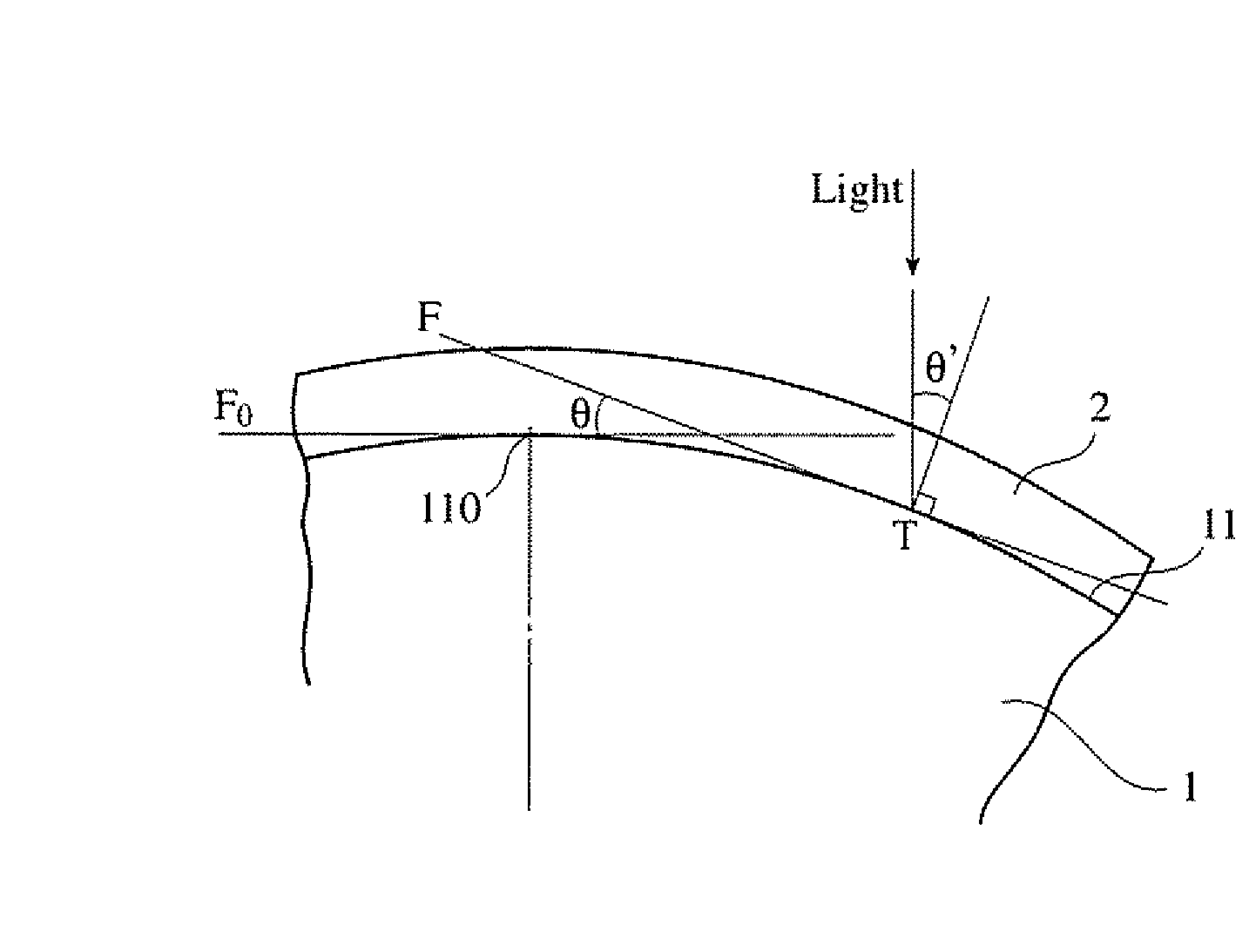
[0063]200 g of aluminum sec-butoxide was mixed with 700 g of sufficiently dehydrated isopropyl alcohol in a low-humidity atmosphere, sufficiently stirred at room temperature, mixed with 105 g of ethyl acetoacetate, and then stirred for 3 hours. At the same time, 300 g of isopropyl alcohol was mixed with 45 g of water in the same atmosphere, and stirred. The resultant aluminum sec-butoxide solution was mixed with an aqueous isopropyl alcohol solution, and stirred at room temperature for 24 hours to prepare a coating liquid. The resultant coating liquid was applied to a convex surface 11 of a lens 1 made of borosilicate crown glass (BK7) having an effective diameter of 3 mm, S / S0(×100) of 62%, and a refractive index of 1.518 (see FIG. 1) by a spin-coating method, cured by heating at a temperature of 150° C. for 2 hours, to obtain a lens coated with a transparent alumina gel layer having a refractive index of 1.38 and a physical thickness of 272 nm. The resultant alumina-gel-coated len...

example 2

[0064]An anti-reflection lens having a petal-shaped alumina layer having three-dimensional average surface roughness (SRa) of 22.3 nm, the maximum roughness height difference (P−V) of 206.0 nm, and a specific surface area (SR) Of 1.26 was produced in the same manner as in Example 1 except for using a lens 1 made of LAK14 glass [effective diameter: 3 mm, S / S0(×100): 62%, refractive index: 1.72]. This anti-reflection lens was examined with respect to transmittance in the same manner as in Example 1. The results are shown in Table 1.


PUM


Abstract

An optical element comprising a lens having a portion with a surface inclination angle of 50° or more within an effective-diameter region, the portion being 10% or more of the effective-diameter region in a projected area, and an anti-reflection coating formed on the lens, the anti-reflection coating having fine roughness with three-dimensional average surface roughness of 5-100 nm on the surface.

Description

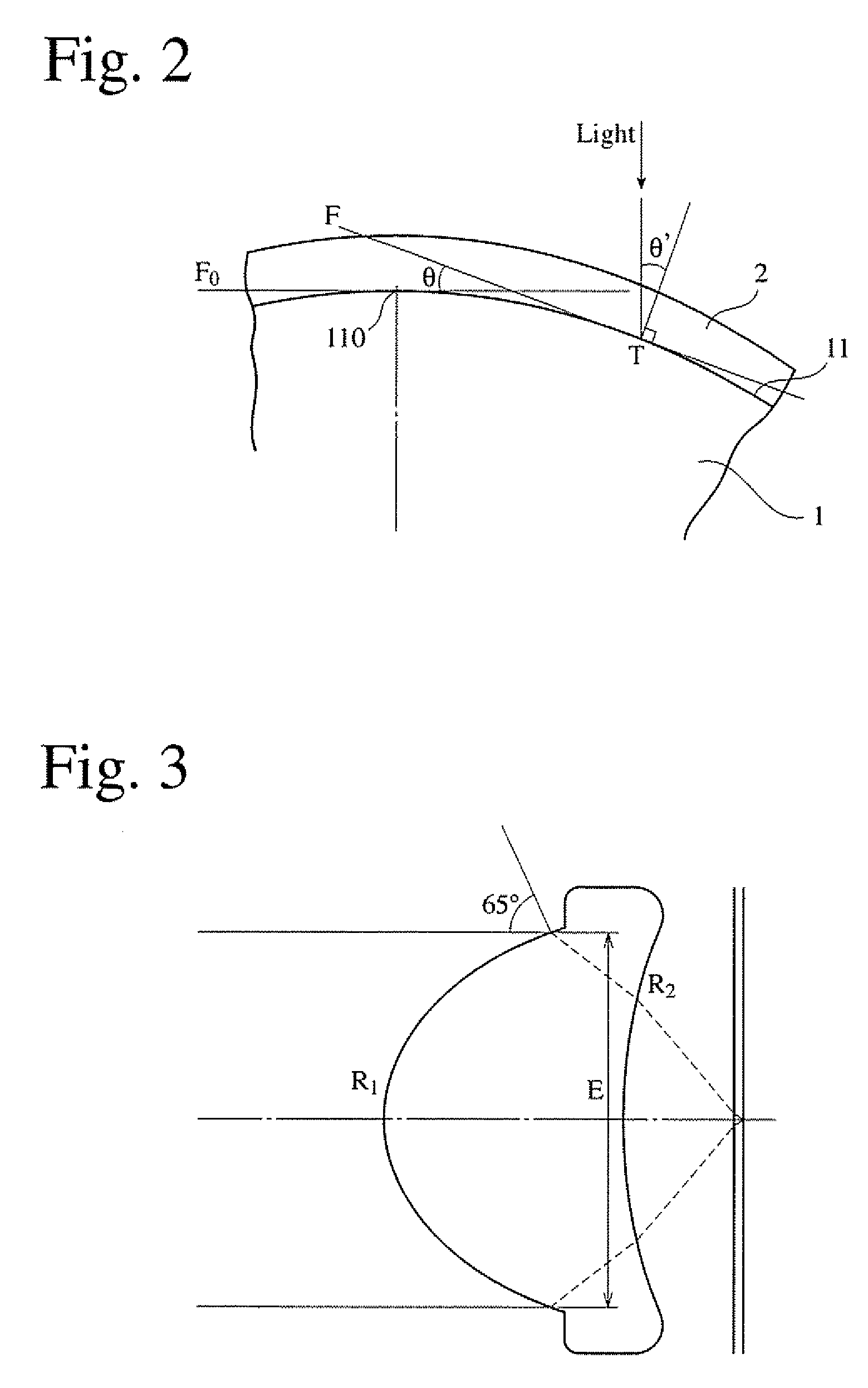
FIELD OF THE INVENTION[0001]The present invention relates to an optical element having an anti-reflection coating, particularly to a high-curvature optical element suitable for light information recording / regenerating apparatuses, semiconductor-developing apparatuses, cameras, endoscopes, light communications parts, etc.BACKGROUND OF THE INVENTION[0002]High-curvature lenses are used as object lenses for light information recording / regenerating apparatuses (light pickup apparatuses) and semiconductor-developing apparatuses. Typical examples of the high-curvature lenses are those having large numerical apertures (NA). Recently proposed are light pickup apparatuses comprising object lenses having NA of 0.85, which are used for laser beams having wavelength of 405 nm. A lens having NA of 0.85 has a shape shown in FIG. 3, for instance. When used as an object lens, laser beams enter into the lens through a surface R1 and exits from a surface R2. Substantially parallel laser beams are vert...

Claims


Application Information

Patent Timeline
Patent Type & Authority Applications(United States)
IPC IPC(8): G02B1/10
CPCC03C17/23C03C2217/214C03C2217/216G02B1/118C03C2217/77C03C2218/113G02B1/113C03C2217/732G02B1/10G02B3/00
Inventor YAMADA, KAZUHIROSAKAI, YASUHIRONAKAYAMA, HIROYUKIYAMADA, MAKI
Owner HOYA CORP
Learn More