
Carrying Devices for Rf Tokens

a technology of carrying devices and tokens, applied in the field of carrying devices, can solve the problems of less sophisticated rfid chips, chip no more than providing a means, and negative environmental impa

Inactive Publication Date: 2008-08-14
OSHEA STEVEN GARY
View PDF5 Cites 39 Cited by
  • Summary
  • Abstract
  • Description
  • Claims
  • Application Information

AI Technical Summary

Benefits of technology

[0021]Preferably the electrically conductive linings are made from a metal foil that sufficiently surround the RF token and be of adequate thickness as to reduce the electrometric field and thus prevent the RF token from being powered and therefore unable to transfer data.
[0030]In yet another form one or more of the RF tokens are not shielded from electromagnetic radiation when the device is closed thus allowing said unshielded token to be presented to a reader without opening the device, whilst at the same time shielding RF tokens contained within said carrying device.

Problems solved by technology

In their simplest form, these chips do nothing more than provide a means to remotely identify an object to which they are attached.
While RFID chips are generally less sophisticated than smartcards, they are still capable of being powered up and interrogated without the owner's knowledge.
First, most battery chemistries contain heavy and toxic metals and since these cards will routinely be lost or discarded, embedding a power source in the card would result in a negative environmental impact.
Second, these cards are projected to be manufactured by the billions worldwide and any product that is produced in these numbers is extremely sensitive to manufacturing costs; Incorporating a battery into the card is simply too costly.
The problem with shielding only the antenna is that the antenna can couple capacitively to the shield in such a way that the shield itself becomes an antenna.
However this shield does not give the user any control over when a data exchange takes place; it merely protects the chip from electrostatic damage and maintains communication with the reader.
Another category of prior art includes bankcard holders, which only protect the card from physical damage.

Method used


Image

  • Carrying Devices for Rf Tokens
  • Carrying Devices for Rf Tokens
  • Carrying Devices for Rf Tokens

Examples


Embodiment Construction

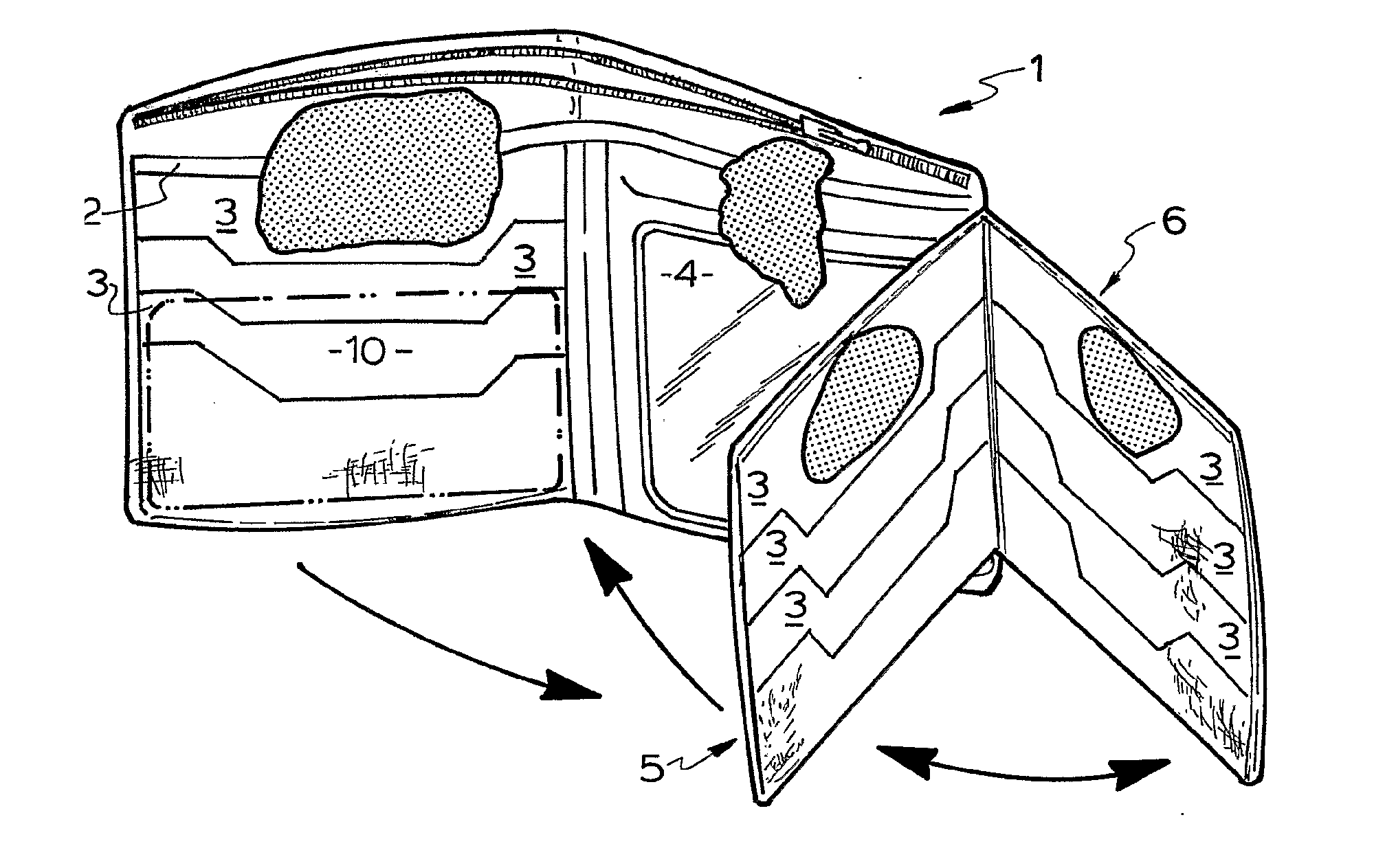
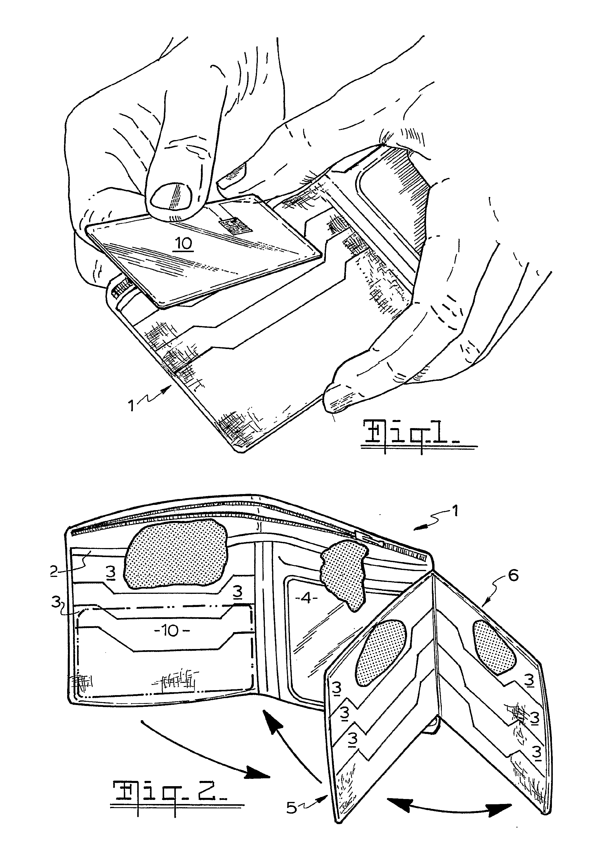
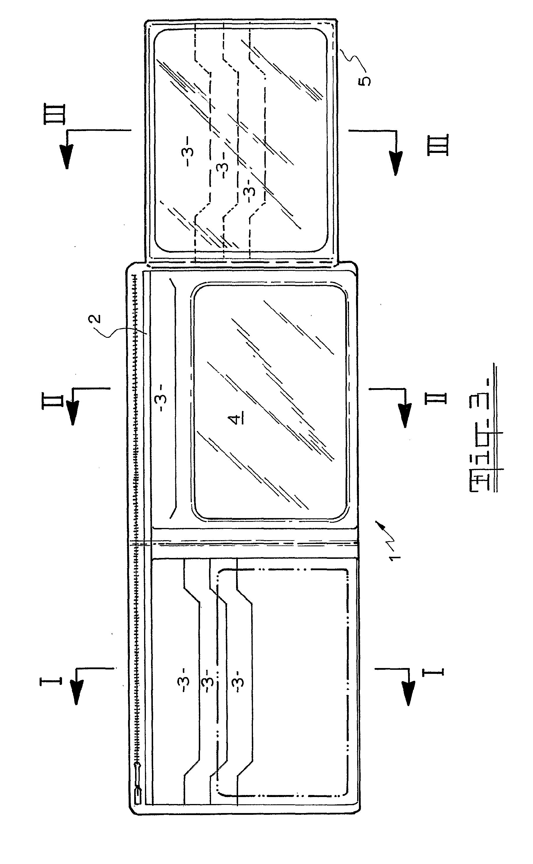
[0037]FIGS. 1 and 2 illustrate a leather wallet 1 which has multiple compartments for holding bank notes, 2, cards 3, and photographs 4. In addition it has, hinged on the right side, two panels 5, 6 which can fold out when wallet 1 is open. Panels 5, 6 also have slots 3 to hold cards.

[0038]FIG. 4 shows in cross section the construction of the left hand section of wallet 1. Outer skin 7 forms a compartment with the body of wallet 1 and is zipped to it by zip 8. This compartment is lined with aluminium foil liner 9 which shields the contents of the closed wallet against electromagnetic radiation. This section also has compartment 2 to hold bank notes and compartments 3 to hold cards.

[0039]FIG. 5 shows in cross section a continuation of this construction in the right hand section of wallet 1 where the continuation of outer skin 7 again forms a compartment with the body of wallet 1 and is zipped to it by zip 8. This compartment is also lined with the continuation of aluminium foil liner...


PUM


Abstract

A carrying device adapted to hold one or more RF tokens and incorporates electrically conductive linings to shield said tokens from each other when the device is open or an unshielded compartment containing an individual token is presented to a reader but which shields the tokens from all electromagnetic radiation when the device is closed. The linings are made from a metal foil or other conductive material and a typical device has the general construction of a caring case or wallet which has compartments to hold sundries, bank notes, cards and visual material and in particular to hold RFID tags and contact-less cards. The wallet or case may also contain one or more panels adapted to hold RFID tags and contact-less cards and to fold out of the wallet when the latter is open allowing individual RF tokens to be presented to a reader.

Description

FIELD OF INVENTION[0001]This invention relates to carrying devices such as a wallet adapted for storing radio frequency tokens such as contact-less radio frequency smart cards and identity tags which in normal use shield the token from electromagnetic radiation but also allow it to be presented to a reader when required.BACKGROUND OF THE INVENTION[0002]Developments in radio frequency (RF) technology are evolving at a rapid pace with contact-less integrated circuit cards (ICCs) and RF identity (RFID) tags now in wide use. These RF devices provide speed and convenience of use since they can be presented to a reader at a distance but this same feature can also be used by unauthorized parties to read the data stored on said tokens.[0003]To date the smart card industry has developed the following technologies which operate without engaging the contact interface:[0004]Close-coupled (ISO / IEC 10536-0-1 mm range), have no metallic contacts but must be physically touched on a reader. These ar...

Claims


Application Information

Patent Timeline
Patent Type & Authority Applications(United States)
IPC IPC(8): A45C1/06
CPCG06K19/07327A45C1/08
Inventor O'SHEA, STEVEN GARY
Owner OSHEA STEVEN GARY
Learn More