
Method of multiplexed analysis using ion mobility spectrometer

a mobility spectrometer and multiplexing technology, applied in the field of improved methods for analyzing ions, can solve the problems of difficult to achieve the effect of producing a high-sensitivity ims-ms, difficult to perform in-depth proteomic studies involving several hundred individual human blood plasma samples, and difficult to achieve the effect of effective discovery of low-level candidate biomarkers in such biological fluids

Active Publication Date: 2008-08-07
BATTELLE MEMORIAL INST
View PDF7 Cites 52 Cited by
  • Summary
  • Abstract
  • Description
  • Claims
  • Application Information

AI Technical Summary

Benefits of technology

[0010]These and other objects of the present invention are achieved by providing a method for analyzing analytes from a sample introduced into an spectrometer. Spectrometers that may take advantage of the present invention include, but are not limited to, ion mobility spectrometers, capillary electrophoresis spectrometers, mass spectrometers, liquid chromatographs, and the like. As is typical in the operation of spectrometers, the present invention begins with the step of introducing analytes into the spectrometer. In the present invention, this is accomplished with a gate that is either open, allowing analyte into the spectrometer, or closed, thereby preventing analyte from entering the spectrometer.
[0011]For example, in the case of an ion mobility spectrometers, the present invention is a method for analyzing an ion beam from a sample introduced into an ion mobility spectrometer. As is typical in the operation of ion mobility spectrometers, the present invention begins with the step of accumulating ions in an ion trap having a gate from the sample provided to the ion mobility spectrum as an ion beam. The present invention then generates a pseudo random sequence of a modulation bins.
[0012]As used herein, a “modulation bin” simply refers to a defined segment of time. While not meant to be limiting, a modulation bin may be coded in a vector. For example, and also not meant to be limiting, the pseudorandom series of modulation bins of the present invention may be coded as a series of ones and zeros in a vector, where a one represents a modulation bin (or period of time) that contained a gate open event, and a zero represents a modulation bin (or period of time) that did not contain a gate open event. A “gate open event” in the context of an ion mobility spectrometer is simply a period of time that the gate of the ion trap is open, thereby allowing ions accumulated in the trap to pass further into the ion mobility spectrometer, and a “gate closed event” in the context of an ion mobility spectrometer is simply a period of time that the gate of the ion trap is closed, thereby allowing ions to accumulate in the trap.
[0013]As will be recognized by those having ordinary skill in the art, it is not necessary to have a trap, or to accumulate ions in the trap, of an ion mobility spectrometer. Further, other spectrometers are operated without traps. Thus, in those contexts, a gate open event, simply means an event where anlayte is being introduced into the spectrometer, and a gate closed event, simply means an event where anlayte is not being introduced into the spectrometer.
[0014]According to the example, a vector representing a pseudorandom sequence of modulation bins would thus consist of a series of ones and zeros in a pseudorandom sequence in which a “1” corresponded to the periods of time during which the gate to the ion trap was opened, and a “0” corresponded to periods of time during which the gate to the ion trap remained closed. It is important to note that modulation bin represented by a “1” would not correspond to the entire period of time during which the gate to the ion trap was open, but rather to a period of time which included a smaller period of time during which the gate to the ion trap was opened. Thus, a modulation bin represented by a “1” would include both a period of time during which the gate to the ion trap was open, and also a period of time during which the gate to the ion trap was closed.
[0015]As used herein, a “pseudorandom sequence” is a sequence that appears random but is not. Typically, pseudorandom sequences exhibit statistical randomness but are generated by an entirely deterministic causal processes, such that that they are easier to produce than a genuine random sequences, and have the benefit that they can be used again and again to produce exactly the same sequences.

Problems solved by technology

Protein detection and identification in a variety of important biomedical applications, including discovery of candidate biomarkers in human blood plasma for early cancer detection, represents a significant analytical challenge for condensed phase multidimensional separations coupled to MS, as many proteins of interest are expected at abundance levels far below that of higher abundance proteins.
1, 845-867) The large dynamic range of interest (>1010), coupled with issues that derive from biological variation, has greatly hindered proteomic approaches for effectively discovering low level candidate biomarkers in such biological fluids.
At present, for example, it is not practical to perform in-depth proteomic studies involving several hundred individual human blood plasma samples.
Anal. Chem., 1997, 69, 3959-3965, Hoaglund, C. S.; Valentine, S. J.; Counterman, A. E.; Clemmer, D. E. Anal. Chem., 1998, 70, 2236-2242) Despite its attractiveness for higher throughput proteomic studies, the application of IMS-MS has been limited by low sensitivity primarily arising from ion losses at the IMS-MS interface and low duty cycle.
(Koeniger, S. L., Merenbloom, S. I., Valentine, S. J, Jarrold, M. F., Udseth H. R., Smith, R. D., Clemmer, D. E. Anal. Chem., 2006, 78, 4161-4174) Though ion transmission drastically improved as compared to earlier implementations of IMS-oTOF design, lower efficiency of ion trapping / accumulation in the ion funnel still limits the ion utilization efficiency or duty cycle.
Anal.Chem., 1999, 71, 5444-5446) CE multiplexing was achieved by photodegradation of a light-absorbing analyte, an approach that would be difficult to implement with a complex biological sample.
Known limitations of the IMS-TOF MS platforms that presently mitigate this attraction include the need for extensive signal averaging due to factors that include significant ion losses in the IMS-TOF interface and an ion utilization efficiency of less than ˜1% with continuous ion sources (e.g., ESI).

Method used


Image

  • Method of multiplexed analysis using ion mobility spectrometer
  • Method of multiplexed analysis using ion mobility spectrometer
  • Method of multiplexed analysis using ion mobility spectrometer

Examples


Embodiment Construction

[0036]A series of experiments were conducted to illustrate the operation of a preferred embodiment of the present invention.

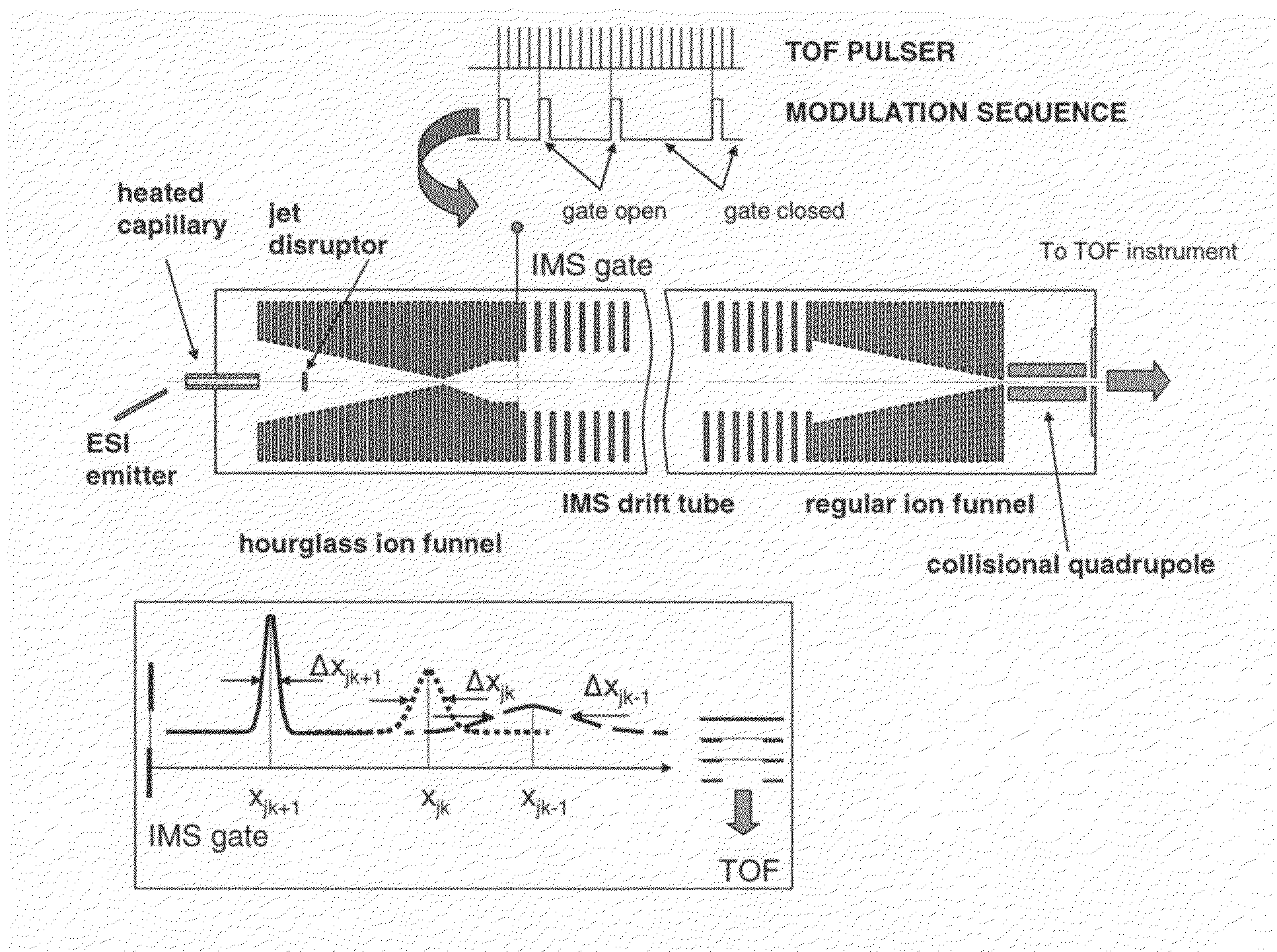
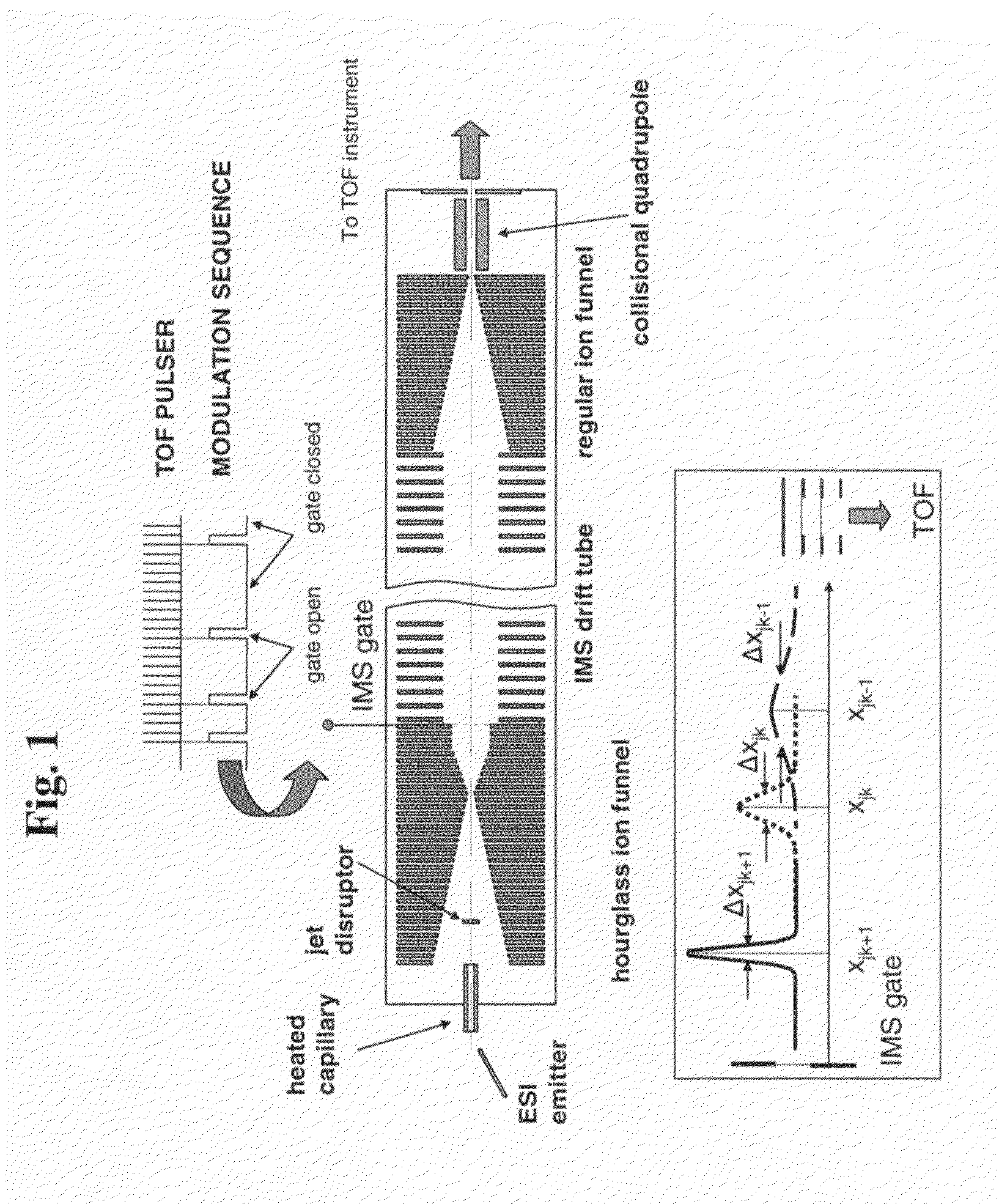
[0037]The multiplexed IMS-TOF MS approach of the present invention has been implemented using two commercial orthogonal TOF instruments; a Q-Star Pulsar (Sciex, Toronto, Canada) and an Agilent TOF (Agilent, Santa Clara, Calif.) arranged as shown in FIG. 1. The design of the ESI source and IMS drift tube coupled to both TOF spectrometers was as described in Tang, K.; Shvartsburg, A. A.; Lee, H.-N.; Prior, D. C.; Buschbach, M. A.; Li, F.; Tolmachev, A. V.; Anderson, G. A.; Smith, R. D. Anal. Chem., 2005, 77, 3330-3339. The ESI source incorporated a 50-um-i.d. fused silica tip electrospraying into a 64 mm-long 430-um i.d. heated inlet capillary operating at a temperature of ˜120° C. The ESI emitter was mounted on a 2D translation stage enabling fine position adjustment with respect to the inlet. All voltages in the ESI source were referenced to a 4 kV potential ap...


PUM


Abstract

A method for analyzing analytes from a sample introduced into a Spectrometer by generating a pseudo random sequence of a modulation bins, organizing each modulation bin as a series of submodulation bins, thereby forming an extended pseudo random sequence of submodulation bins, releasing the analytes in a series of analyte packets into a Spectrometer, thereby generating an unknown original ion signal vector, detecting the analytes at a detector, and characterizing the sample using the plurality of analyte signal subvectors. The method is advantageously applied to an Ion Mobility Spectrometer, and an Ion Mobility Spectrometer interfaced with a Time of Flight Mass Spectrometer.

Description

GOVERNMENT RIGHTS[0001]The invention was made with Government support under Contract DE-AC0676RLO 1830, awarded by the U.S. Department of Energy. The Government has certain rights in the invention.TECHNICAL FIELD[0002]This invention relates to improved methods for analyzing ions. More specifically, this invention relates to improved methods for analyzing ions using an ion mobility spectrometer, either alone or in combination with a time-of-flight mass spectrometer.BACKGROUND OF THE INVENTION[0003]Since its introduction as an analytical technique in early 1970s, (Karasek, F. W. Anal. Chem., 1974, 46, 710A-717A) ion mobility spectrometry (IMS) has been increasingly applied to the characterization of gas-phase ions in a number of applications, including quality control in semiconductor manufacturing processes, (Carr, T. W. Thin Solid Films, 1977, 45, 115-122) environmental monitoring of air and water, (Eiceman, G. A.; Garcia-Gonzalez, L.; Wang, Y.-F.; Pittman, B. Talanta, 1992, 39, 459...

Claims


Application Information

Patent Timeline
Patent Type & Authority Applications(United States)
IPC IPC(8): H01J49/04
CPCH01J49/0031G01N27/622G01N27/623
Inventor BELOV, MIKHAIL E.SMITH, RICHARD D.
Owner BATTELLE MEMORIAL INST
Learn More