
Vehicle travel control system

a technology of vehicle travel control and control system, which is applied in the direction of electric devices, instruments, etc., can solve the problems of reducing correctness, reducing recognition, judgment and operation, and reducing attention of drivers, so as to increase safety during the cruise control

Active Publication Date: 2008-08-07
DENSO CORP
View PDF12 Cites 59 Cited by
  • Summary
  • Abstract
  • Description
  • Claims
  • Application Information

AI Technical Summary

Benefits of technology

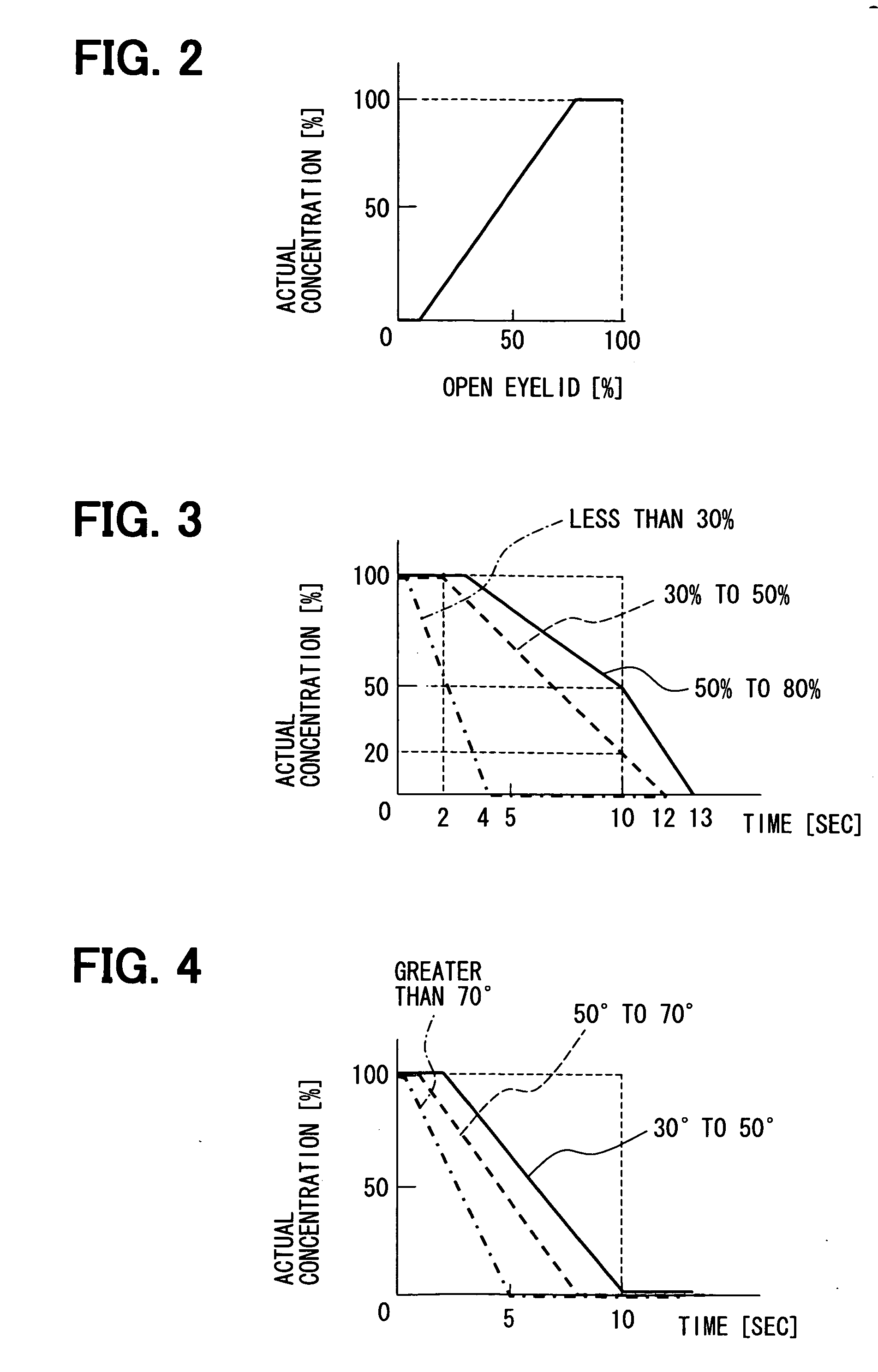
The present invention is a vehicle travel control system that can increase safety during cruise control. It automatically drives the vehicle without the driver's operation and detects the driver's concentration degree based on their state. The control content is changed accordingly to ensure safe driving. Additionally, the system takes into account the surrounding environment of the vehicle to determine the required concentration degree for safe driving.

Problems solved by technology

Particularly, when the cruise control last long, driver's attention may be distracted or lowered.
At this time, when the driver is low in concentration, a delay in recognition, judgment, and operations, and reduction in correctness may occur.
However, when a situation change that requires operation intervention by the driver occurs, again, a delay in recognition, judgment, and operations, and reduction in correctness may occur.

Method used


Image

  • Vehicle travel control system
  • Vehicle travel control system
  • Vehicle travel control system

Examples


first embodiment

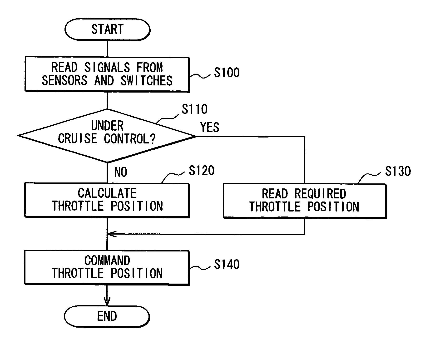
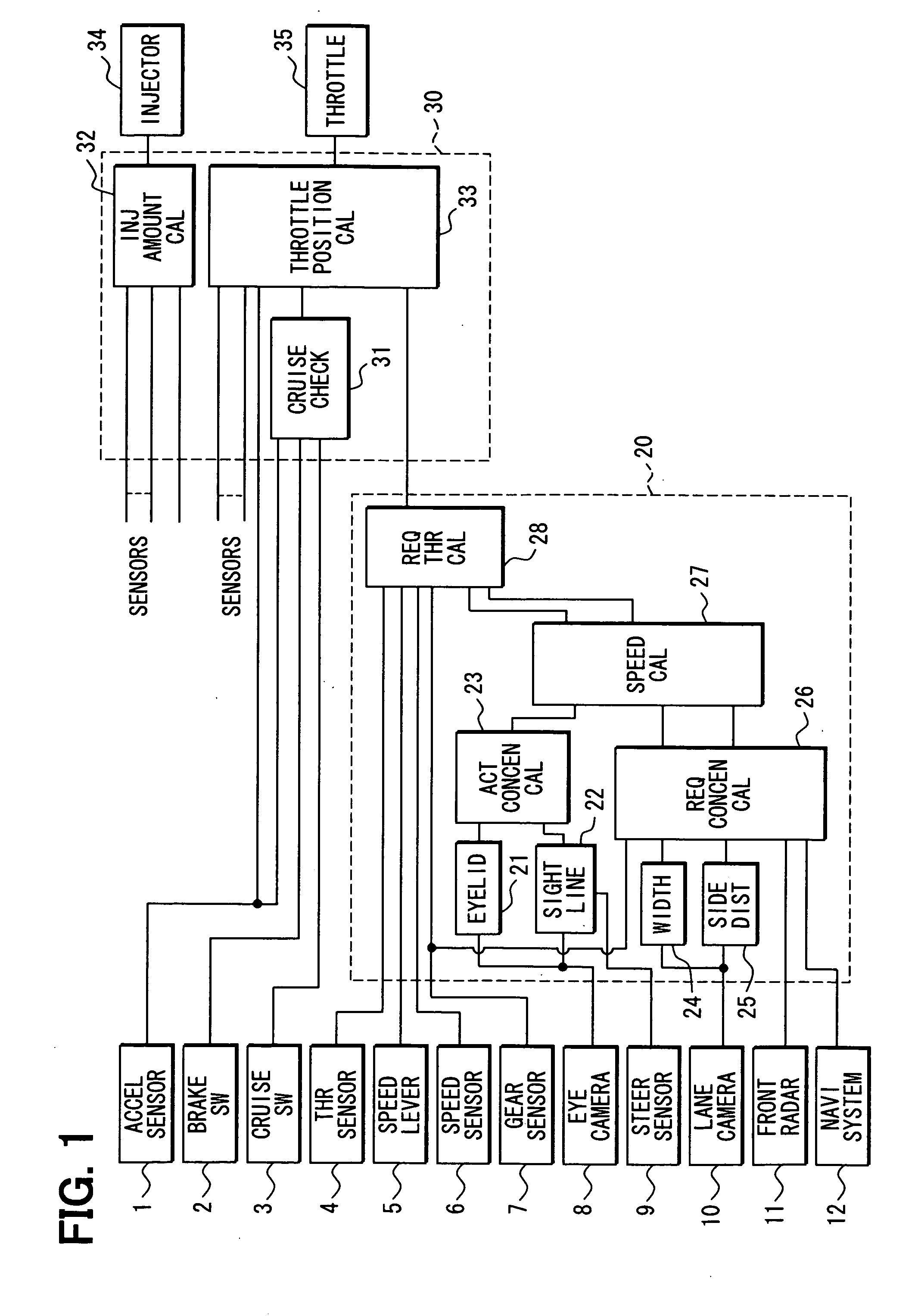
[0032]As shown in FIG. 1, a vehicle travel control system mounted on a subject vehicle includes various sensors and switches, an auto-cruise (electronic control unit) ECU 20, and an engine control ECU 30. With respect to the auto-cruise ECU 20 and the engine control ECU 30, functions performed by the ECUs 20 and 30 are shown as functional blocks.

[0033]The engine control ECU 30 receives signals from an accelerator position sensor 1, a brake switch 2, and a cruise control actuation switch 3, in addition to signals from various sensors. The accelerator position sensor 1 outputs a detection signal corresponding to the depression amount of an accelerator pedal (not shown) by the driver of its subject vehicle (subject vehicle). The brake switch 2, when a brake pedal (not shown) is depressed by the driver, outputs a brake operation signal. The cruise control actuation switch 3 outputs a signal indicating the start or end of the cruise control function. The cruise control actuation switch 3...

second embodiment

[0100]The vehicle travel control system of the second embodiment is directed to adaptive cruise control, which performs control to follow a preceding vehicle, if any, at a specific vehicular distance. This system is shown in FIG. 17, in which the same components as in the first embodiment are assigned the same reference numerals.

[0101]As shown in FIG. 17, the vehicle travel control system includes a brake control ECU 40 in addition to an ACC-ECU 20a as an adaptive cruise controller and an engine control ECU 30a. This is because the subject vehicle has to be not only accelerated but also decelerated to follow a preceding vehicle while maintaining a specific vehicular distance relative to the preceding vehicle.

[0102]The configuration of the engine control ECU 30a and signals inputted to the engine control ECU 30a are almost the same as those of the engine control ECU 30 in the first embodiment. However, the vehicle travel control system of this embodiment performs adaptive cruise cont...


PUM


Abstract

A vehicle travel control system includes a cruise control ECU, an engine control ECU and a brake control ECU. The cruise control ECU checks whether a driver's actual concentration degree is insufficient relative to a required concentration degree in terms of safety in surrounding environments of the subject vehicle. When such possibility arises, even during the cruise control, the speed of the subject vehicle is controlled to match a control vehicle speed lower than a set vehicle speed or a control distance to a preceding vehicle.

Description

CROSS REFERENCE TO RELATED APPLICATION[0001]This patent application relates to and incorporates herein Japanese Patent Applications No. 2007-27186 filed on Feb. 6, 2007 and No. 2007-306452 filed on Nov. 27, 2007.FIELD OF THE INVENTION[0002]The present invention relates to a vehicle travel control system that can enhance safety during cruise control operation of a vehicle by a device performing the cruise control, wherein the cruise control allows automatic cruise of the vehicle without requiring operations on an accelerator pedal and a brake pedal by a driver.BACKGROUND OF THE INVENTION[0003]As devices performing cruise control of a vehicle, auto-cruise control and adaptive cruise control are disclosed in e.g., US 2004 / 0040765 (JP 2004-90712A) and U.S. Pat. No. 5,969,969 (JP 2003-272100A), respectively. The auto-cruise control allows a vehicle to travel at a driver-set vehicle speed, and the adaptive cruise control allows a vehicle to travel to follow a preceding vehicle while keepi...

Claims


Application Information

Patent Timeline
Patent Type & Authority Applications(United States)
IPC IPC(8): B60W40/08B60W30/14B60W30/16B60W10/18
CPCB60W10/04B60W10/184B60W30/16B60W2550/20B60W40/08B60W2040/0818B60W2540/22B60W40/04B60W2554/00B60W2540/221B60W2554/4047
Inventor KONDOH, TOSHIYUKI
Owner DENSO CORP
Learn More