
Process for the Thermal Treatment of Pharmaceutical Waste Material

a waste material and thermal treatment technology, applied in the field of waste material thermal treatment, can solve the problems of not all components of the waste stream present sufficient economic value, not all parts of the waste stream are suitable for compost production, and the volume of the treated waste material recovered after the process may be about 90% reduced

Inactive Publication Date: 2008-07-31
PHASE SEPARATION SOLUTIONS
View PDF4 Cites 14 Cited by
  • Summary
  • Abstract
  • Description
  • Claims
  • Application Information

AI Technical Summary

Benefits of technology

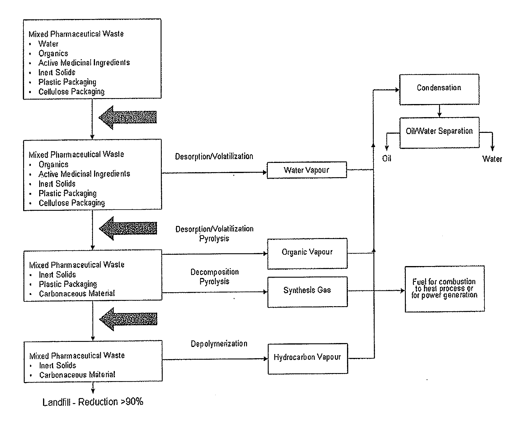
[0006]The inventors have developed a process that combines desorption, depolymerization and pyrolysis for the treatment of waste materials, particularly pharmaceutical waste materials. The material to be treated is placed in a reaction chamber and subjected to a three-stage gradient temperature, without any need to circulate the material. The process ensures residence time at such temperatures as to thermally destroy the medicinal ingredients. The process also allows for a continuous recovery of oil, water as well as non-condensable synthesis gas that can be used as heating source for the process. The process yields a solid residue of significantly reduced size that is suitable for safe landfilling.

Problems solved by technology

These processes have some benefits but also present significant disadvantages.
For example, not all components of the waste stream present sufficient economic value to justify a recycling program.
Also, not all components of the waste stream are suitable for compost production.
And incineration is widely known as requiring high levels of energy and sophisticated equipment as well as producing airborne emissions; moreover incineration does not allow for the recovery of hydrocarbons.

Method used


Image

  • Process for the Thermal Treatment of Pharmaceutical Waste Material
  • Process for the Thermal Treatment of Pharmaceutical Waste Material

Examples


Embodiment Construction

[0021]As used herein and in the claims, the following terms have the meaning and definition set out below.

[0022]The term “pyrolysis” is meant to encompass processes wherein the atmosphere in the pyrolysis chamber may contain a small amount of air (oxygen), but the amount is so small that there is no visible combustion. Although the term “pyrolysis” is generally defined as the “transformation of a compound into one or more substances by heat alone, i.e., without oxidation” (Hawley's Condensed Chemical Dictionary, 13th Ed. (1997).), it is envisaged that at least a small amount of oxygen may be present into the chamber during the process according to the invention. Indeed, some air may enter the chamber during the loading of the waste. Also some air may be entrained within the waste. Moreover, as the pressure within the chamber may be slightly negative, a small amount of air may be drawn into the furnace through deficient seals for example.

[0023]The term “waste material” is meant to re...


PUM

PropertyMeasurementUnit
temperatureaaaaaaaaaa

Abstract

There is provided a process for the thermal treatment of waste materials, particularly pharmaceutical waste materials. The process comprises placing the waste material into a chamber and increasing the temperature inside the chamber in three stages. At a first stage, water in the material is desorbed as water vapor. At a second stage, organic ingredients in the material are desorbed and decomposed producing condensable organic vapor and non-condensable synthesis gas. And at a third stage, polymer-based components of the material are depolymerized and decomposed producing condensable hydrocarbon vapor. The non-condensable synthesis gas produced can be used as heating source for the process.

Description

FIELD OF THE INVENTION[0001]The invention relates generally to processes for the thermal treatment of waste materials. In particular, the invention relates to a process for the thermal treatment of pharmaceutical waste materials, and subsequent recovery of oil.BACKGROUND OF THE INVENTION[0002]Disposal of waste materials, in particular hazardous and non-hazardous pharmaceutical and personal consumer product waste, has generally been completed primarily through shredding and landfilling. While shredding removes potential product liability issues such as black market reselling of off-spec and expired products as well as unwanted public visibility of corporate identifiers, the desire to reduce the volume of waste to be landfilled has led to the development of alternative processes such as recycling, composting and incineration. These processes have some benefits but also present significant disadvantages. For example, not all components of the waste stream present sufficient economic va...

Claims


Application Information

Patent Timeline
Patent Type & Authority Applications(United States)
IPC IPC(8): C02F1/10B01D17/09
CPCB09B3/00B09B3/0083B09C1/06C10B53/00C10K1/32C10J3/00C10J2300/0909C10J2300/0916C10J2300/0946C10G1/10Y02P20/145B09B3/40
Inventor CLARKE, STEPHEN
Owner PHASE SEPARATION SOLUTIONS
Learn More