
System and method for supplying power for actuators on board an aircraft

a technology for actuators and aircraft, applied in emergency power supply arrangements, energy-saving board measures, electric devices, etc., can solve problems such as failures, equipment damage, circuit tripping, etc., and achieve the effect of not preventing the high current peak demanded

Inactive Publication Date: 2008-07-24
AIRBUS OPERATIONS (SAS)
View PDF4 Cites 66 Cited by
  • Summary
  • Abstract
  • Description
  • Claims
  • Application Information

AI Technical Summary

Benefits of technology

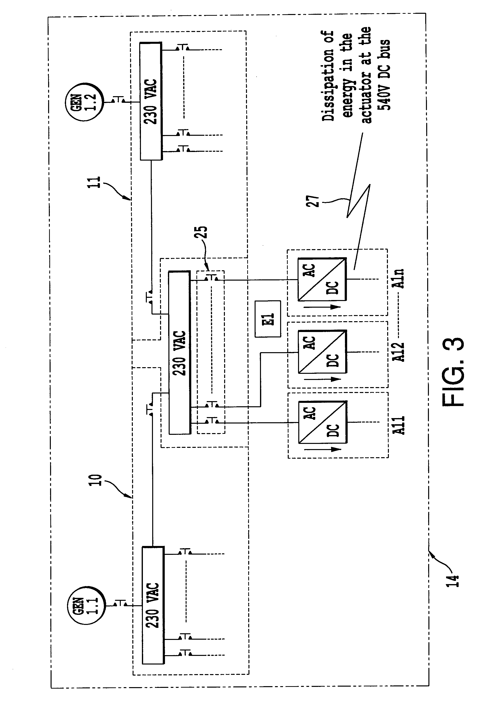
[0060]It is not necessary to dissipate the energy which these generate in the actuators. This energy can be rejected to the direct current network, at various levels and by various means. Thermal stresses are reduced, as are volume and density. Reliability is improved.
[0061]The rectifier in the head of each actuator can be shared, which then permits a reduction of the power sizing. A gain in volume, weight and reliability is again noted here.
[0064]A controlled converter, supplying one or more actuators, can offer, as well as precharging the capacitors, protection of the circuit supplying this or these actuator(s) by controlling the current produced.
[0065]Redundancy of the means of power transfer allows great availability of electricity. This availability is improved still more owing to the technological differences between systems (AC / DC rectifiers, DC / DC converters, etc.).
[0066]The risks of instabilities of direct current networks are avoided thanks to using static converters between the various points of each network.

Problems solved by technology

Such a rectifier is not reversible in power.
If the actuators are switched on simultaneously, the large number of simultaneous calls for current can create faults (circuits tripping) or even damage to equipment.
Moreover, this does not prevent the high current peaks demanded by each actuator.
A technical problem which arises is thus that of:handling the reversibility in power of the actuators to avoid heating; andhandling the switching on of the actuators to avoid calls for current.

Method used


Image

  • System and method for supplying power for actuators on board an aircraft
  • System and method for supplying power for actuators on board an aircraft
  • System and method for supplying power for actuators on board an aircraft

Examples


specimen embodiment

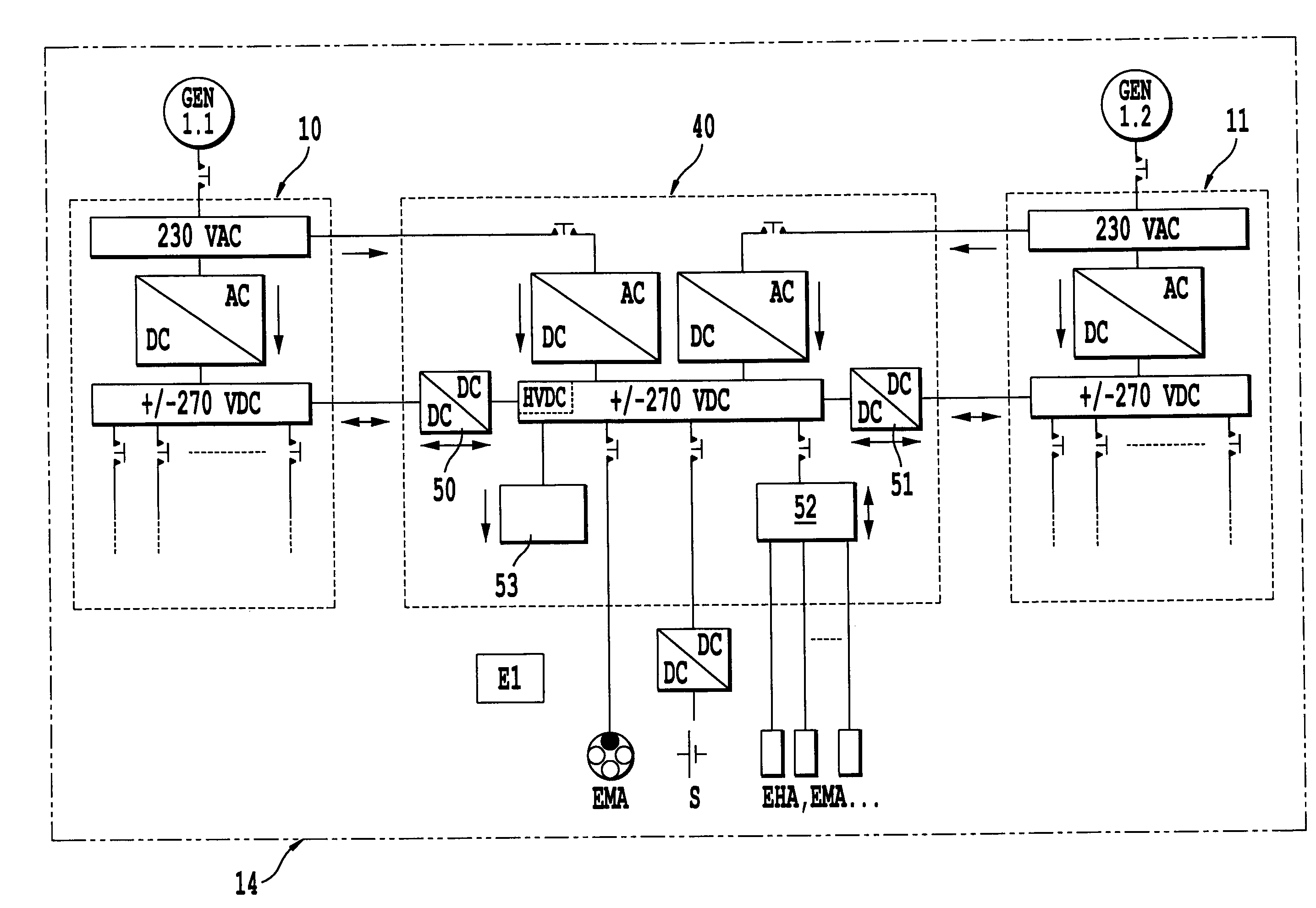
[0162]An example of the detailed architecture for generation and distribution of the electrical circuit E1 is given in FIG. 16. In this example, the devoted master box 40 is connected to two conventional master boxes 10 and 11. In this figure, some loads, viz. a braking actuator EMA and several flight control actuators EHA, EMA, etc. are illustrated by way of example.

[0163]The transfers between the + / −270 volts direct current (DC) from the devoted master box 40 and each conventional master box 10 and 11 are implemented by two DC / DC converters 50 and 51, reversible in power.

[0164]In the devoted master box 40, the bus controller 52 placed between the HVDC busbar and the flight control actuators can be formed by one or more DC / DC converters. As mentioned above, this or these converter(s) 52 can play a double role of capacitor precharger and protection. In the devoted master box 40, there is also a surge suppressor 53.

[0165]Below will be analysed successively several methods of supplyin...


PUM


Abstract

The invention relates to a system and a method for supplying power to an aircraft comprising several generators supplying alternating current to several different primary electrical master boxes (10, 11, 12 and 13), the various aircraft loads being connected to each of these master boxes. This system comprises conventional master boxes (10, 11, 12 and 13) which supply power loads and at least one master box (40, 41) devoted to actuator loads, this at least one devoted master box being connected to conventional master boxes.

Description

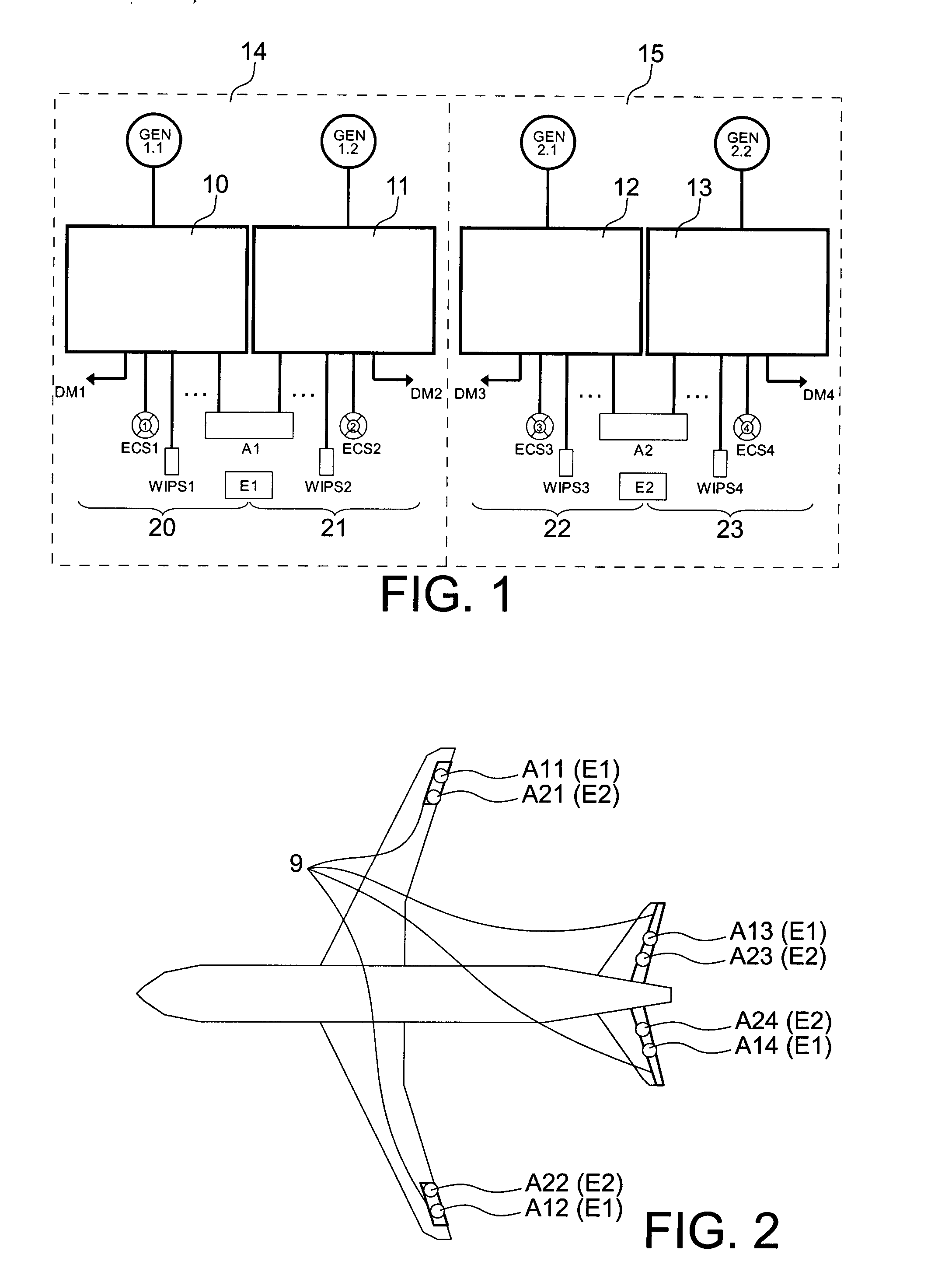
TECHNICAL FIELD[0001]The invention relates to a system and method for supplying power for actuators on board an aircraft, for example an airplane.[0002]In what follows, an aircraft of the airplane type will be considered in order to simplify the description.STATE OF THE PRIOR ART[0003]The increase in electrical energy used on future airplanes is leading to an increase in the number of generators and electrical master boxes. An example of an architecture for generating and distributing electricity in such an airplane is given in FIG. 1. This shows four generators GEN 1.1, GEN 1.2, GEN 2.1 and GEN 2.2 supplying alternating voltage (for example 230V AC) to four separate electrical master boxes 10, 11, 12 and 13 for a first and second side 14 and 15 of the airplane. The airplane's various electricity consumers (loads) are connected to each of these master boxes. For example, the loads 20, 21, 22 and 23, appearing on this FIG. 1, are typical of a “more electric” airplane without drawing ...

Claims


Application Information

Patent Timeline
Patent Type & Authority Applications(United States)
IPC IPC(8): B64D33/00H02J3/02H02J3/38
CPCH02J1/08H02J1/12Y02T50/54Y02T50/545B64D2221/00H02J1/14H02J2310/44Y02T50/50
Inventor LANGLOIS, OLIVIERFOCH, ETIENNEPRISSE, LUCIENROBOAM, XAVIER
Owner AIRBUS OPERATIONS (SAS)
Learn More