
Container and Congruent Scoop Assembly

a scoop assembly and container technology, applied in the field of packaging, can solve the problems of spillage as the contents fall away from the lid or top, the current packaging is difficult to handle with a single hand, and the container lid or top is difficult to locate and remove the scoop, so as to achieve easy and clean access

Inactive Publication Date: 2008-07-24
ABBOTT LAB INC
View PDF6 Cites 42 Cited by
  • Summary
  • Abstract
  • Description
  • Claims
  • Application Information

AI Technical Summary

Benefits of technology

The container minimizes spillage and contamination, allows easy access to the last bits of product without inverting, and maintains product integrity across varying altitudes and pressures, while being durable and convenient to handle and stack.

Problems solved by technology

Consumers or users of such containers have found that the current packaging is difficult to handle with a single hand, and have found that it is difficult to open the container and to locate and remove the scoop from the packaging upon the first use without experiencing spillage.
Once the lid of the container is removed and / or opened, the contents are often loosely caked or packed into parts of the interior of the lid or top of the container, which leads to spillage as the contents fall away from the lid or top.
While some of the falling powder may fall back into the interior of the container, much of it is wasted and contaminated as it spills onto the surrounding workspace.
Additionally, prior containers do not offer adequate sealing of the contents after the container has been opened for the first time.
This leads to the undesirable and inadvertent leaking or escape of the contents from various poorly sealed areas of the container.
This search and locate process contaminates the contents and soils the hands of the user, which can lead to more unwanted spillage as the powder-coated fingers and hands are removed from the interior of the container.
As the coating of powder and the packed bowl of powder loosen during the removal process, more contents are contaminated and wasted as the coating falls away from the hands, fingers, and scoop, and as any powder caked in the bowl loosens and falls.
Additional problems have been experienced with scoops that are positioned in a more convenient location, perhaps against an interior or exterior wall.
These additional problems include difficultly in grasping the scoop, which may be tightly fastened with adhesive against the wall and / or with a mechanical retainer or fastener that leaves very little clearance between the scoop and surrounding structure of the container for grasping the scoop.
These undesirable configurations typically will require more than one free hand for removal and grasping of the scoop.
Users have also found that it is difficult to remove the last bit of powder from the nearly empty container because the shape of the container includes tight and closed spaces that are inaccessible to the scoop, and which has other areas having a shape that is different than the shape of the scoop.
As a result, a user must resort to inverting the container to completely empty the contents, which creates another instance of spillage and wasted contents.
Manufacturers of such containers have also experienced a number of challenges in fabricating the containers when using various types of optionally preferred thermo-forming and polymeric manufacturing processes and materials.
Those skilled in the relevant arts have long known about the difficultly in producing various types of packaging containers using thermo-formed polymeric materials.
Such materials are subject to many variables that adversely and unexpectedly result in product components being produced that can vary beyond acceptable dimensional tolerance limits, which results in the need to scrap defective containers and components of such container, and the need to produce replacements.
Also, polymeric materials can render mis-shaped component profiles due to unexpected shrinkage and warping, and other thermo-forming anomalies that leave entire production runs of containers and components for containers destined for the scrap heap.
These types of manufacturing problems are especially pronounced in containers formed from assemblies that incorporate more than one component, such as where a top or lid and a collar assembly are fastened to a bottom part of the container.
Problems in assembling such components can result if one or both of the components are out of tolerance or otherwise mis-shaped.
Still other users experience problems with prior art containers that are inadequate for use in circumstances where the ambient air pressure external to the container changes drastically so as to create a significant pressure differential between the sealed interior space of the container and the external, ambient atmosphere.
When such sea-level pressure containers are shipped to consumers located at higher altitudes or elevations, the container packaging will have a higher internal pressure, which creates a pressure differential that can be significant.
If the pressure differential is large enough, the container may become distended making it difficult to stack and store, and may even experience a breach, leading to contaminated and wasted product.
Upon opening, ambient air can rush into the interior space of the container and contaminate the contents.
When a container having a pressure differential is opened, the contents may again spill due to the very rapid pressure equalization ejecting a cloud of powdered or other type of product contents.
Attempts to overcome these disadvantages have included thicker walled containers, which increases weight and material costs, as well as round and cylindrical containers that may have higher hoop stress strength, but which are less efficient and convenient to stack and store on a shelf.

Method used


Image

  • Container and Congruent Scoop Assembly
  • Container and Congruent Scoop Assembly
  • Container and Congruent Scoop Assembly

Examples


Embodiment Construction

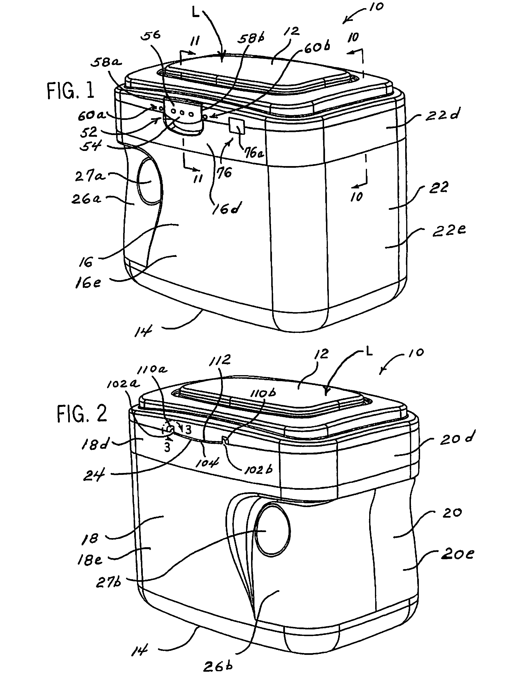
[0086]As used herein, the expression “top wall” means the side of the container exclusive of the bottom wall, the first side wall, the second side wall, the front wall, and the rear wall of the container. Although it is somewhat arbitrary which wall is designated front or rear or side, for purposes of consistency, “rear” is generally used for a wall with a hinge and “front” is used for a wall with a latch mechanism. The term “lid” means a hinged cover for a hollow receptacle and is intended to include either an independently formed and removable lid and other variations that can include the lid alone, the lid and collar assembly, and other variations wherein the lid and / or collar are formed from the top wall of the container plus the upper portion of the first side wall, the upper portion of the second side wall, the upper portion of the front wall, and the upper portion of the rear wall of the container. As used herein, the term “bracket” means a wall-anchored fixture adapted to su...


PUM


Abstract

A container (210) for holding granular / powdered material and formed by a top wall (212), a bottom wall (214), a front wall (216), a rear wall (218), a first side wall (220), and a second side wall (222). A removable lid (D) is interiorly mounted with a scoop (32) and is hinged to a collar (300) that includes a sealing gasket (330). The collar (300) mounts to the walls of the container (210). A sealing wall 240 of the lid (D) cooperates with the gasket (330) to prevent the contents from spilling. The container (210) incorporates sealing features, and a geometry for container wall junctions (50) that can have curvilinear and angled or rectilinear profiles. A scoop 32 is releasably carried in the lid (L, D) and can include a rim portion (36,a,b,c) that can be formed and or flexed to be congruent to the profiles.

Description

PRIORITY CLAIM TO RELATED APPLICATION[0001]This application claims the benefit of the earlier filing date of commonly owned and co-pending U.S. patent application Ser. No. 11 / 645,887 filed Dec. 27, 2006, and No. 61 / 014,595 filed Dec. 18, 2007, both of which are hereby incorporated by reference in their entirety as though fully set forth in the present application.RELATED APPLICATIONS[0002]This application is also related to three other commonly owned and co-pending applications filed on Dec. 26, 2007, concurrently with this application, each incorporated by reference. The titles and inventors are:[0003]CONTAINER WITH GASKET SEAL, invented by James P. Perry, David Compeau, Craig A. McCardell, and Jeremy McBroom and given Ser. No. ______.[0004]CONTAINER WITH SEALING, invented by James P. Perry, David Compeau, Craig A. McCardell, and Jeremy McBroom and given Ser. No. ______.[0005]CONTAINER AND COLLAR WITH ATTACHING MEANS, invented by James P. Perry, Charles R. Schotthoefer, David Compe...

Claims


Application Information

Patent Timeline
Patent Type & Authority Applications(United States)
IPC IPC(8): B65D43/16A47J43/28B65D53/00
CPCB65D25/2897B65D43/163B65D51/20B65D51/246B65D2251/0018B65D2251/0021B65D2543/00796B65D2543/00194B65D2543/00296B65D2543/00537B65D2543/0062B65D2543/00685B65D2543/00759B65D2251/0093B65D43/169B65D51/247B65D51/28B65D2231/005B65D2543/00351B65D2543/00435B65D2543/00564B65D2543/00574B65D2543/00648B65D2543/00694B65D2543/00805B65D2543/00824
Inventor PERRY, JAMES P.GOHLKE, ASHLEY A.HOOK, WILLIAM J.JORDAN, KATHERINE J.CLAY, J. KEVINDARR, RICHARD C.ELDER, JACK E.PEDMO, MARC A.CLARKE, PETER B.
Owner ABBOTT LAB INC
Learn More