
Diamond Cutting Tool and Manufacturing Method Thereof

a cutting tool and diamond technology, applied in the direction of grinding devices, superimposed coating processes, instruments, etc., can solve the problems of diamond particles moving in disarray, so much plating time in order to thicken the plating thickness, and increase the manufacturing cost and time, so as to achieve the effect of shortening the manufacturing tim

Inactive Publication Date: 2008-07-17
PARK RIN SOON
View PDF6 Cites 8 Cited by
  • Summary
  • Abstract
  • Description
  • Claims
  • Application Information

AI Technical Summary

Benefits of technology

[0009]Accordingly, the present invention has been made to solve the above-mentioned problems occurring in the prior art, and an object of the present invention is to provide a diamond cutting tool in which the diamond particles are securely adhered to a disc type body portion and a manufacturing time is shortened, and a manufacturing method thereof.
[0010]Another object of the present invention is to provide a diamond cutting tool in which the diamond particles are coated with magnetic metal and a body portion is magnetized so that the diamond particles coated with metal are fixed to the magnetized body portion through a magnetic force therebetween, thereby preventing the diamond particles from being in disarray, and a manufacturing method thereof.
[0011]Still another object of the present invention is to provide a diamond cutting tool in which the diamond particles coated with metal are arranged in multi-layer using a magnetic force and electro-deposited on a body portion, thereby prolonging a lifetime of the cutting tools, and a manufacturing method thereof.Technical Solution
[0017]The diamond particles may be arranged in multi-layer and electro-deposited so that the diamond particles are thickened to prolong a lifetime of the cutting tool.

Problems solved by technology

This causes a problem of complicated manufacturing process so that manufacturing cost and time are increased.
However, according to this conventional manufacturing method, there was a problem in that it takes so much plating time in order to thicken a plating thickness for secure adhesion of the diamond particles.
In addition, according to the conventional manufacturing method, there was another problem in that the diamond particles are moved to be in disarray in the course of electro-deposition of the diamond particles after the arrangement of the diamond particles on the body portion.

Method used


Image

  • Diamond Cutting Tool and Manufacturing Method Thereof
  • Diamond Cutting Tool and Manufacturing Method Thereof
  • Diamond Cutting Tool and Manufacturing Method Thereof

Examples


Embodiment Construction

[0030]Hereinafter, preferred embodiments of the present invention will be described with reference to the accompanying drawings.

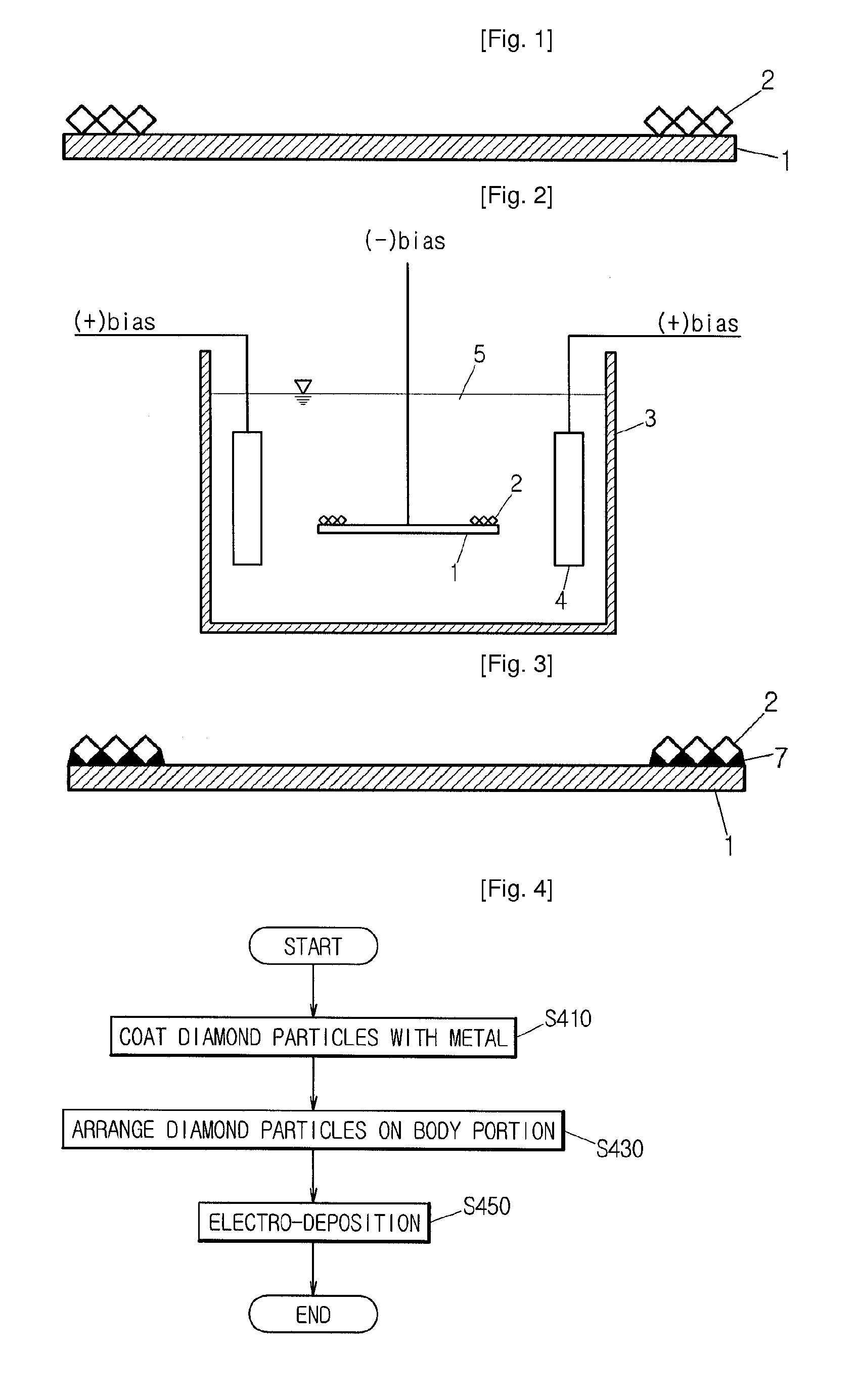
[0031]FIG. 4 is a flow chart showing a manufacturing method for a diamond cutting tool according to a preferred embodiment of the present invention. As shown in FIG. 4, the manufacturing method for a diamond cutting tool according to the present invention comprises the steps of coating the diamond particles with metal (S410), arranging the metal coated diamond particles on a body portion (S430), and electro-depositing the diamond particles on the body portion (S450).

[0032]Description will be made in detail to the steps of the manufacturing method for the diamond cutting tool according to the present invention.

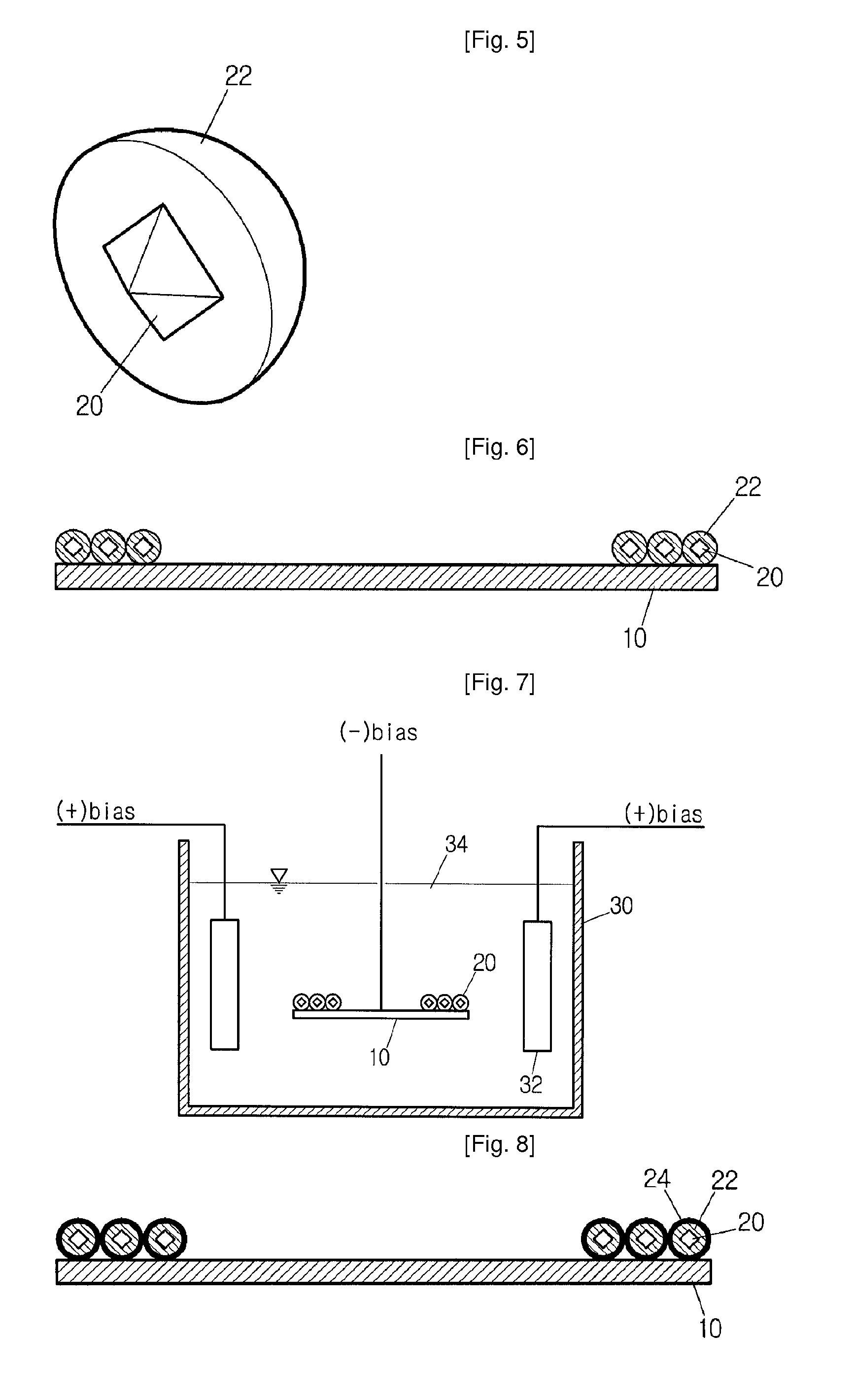
[0033]FIG. 5 is a perspective view of a diamond particle 20 coated with metal 22. As shown in FIG. 5, for manufacturing the diamond cutting tool, a worker first coats the outer surfaces of the diamond particles 20 with metal to form a metal coating lay...


PUM

PropertyMeasurementUnit
magnetic propertyaaaaaaaaaa
magnetic forceaaaaaaaaaa
magnetizationaaaaaaaaaa

Abstract

A manufacturing method of a diamond cutting tool is characterized in that the metal coated diamond particles are arranged on a region of a steel body portion intended to be used as a cutting edge, and then adhered to the body portion through the electro-deposition whereby the manufacturing time is reduced, the diamond particles are securely adhered to the body portion, and the lifetime of the cutting tool is prolonged as well.

Description

TECHNICAL FIELD[0001]The present invention relates to a diamond cutting tool and a manufacturing method thereof, and more particularly to diamond cutting tool which can be shortened in manufacturing time and prolonged in lifetime and a manufacturing method thereof.BACKGROUND ART[0002]In general, the diamond cutting tool has been used as a cutting tool for cutting a hard material such as stone, metal, concrete, and the like in the construction field or engineering works.[0003]As a manufacturing method of the diamond cutting tool, there has been known a method in which a plurality of cutting segments that is manufactured by a blending, a forming, and a sintering of diamond particles and metal powders is welded around a body portion made of a high speed tool steel such as a carbon tool steel, a low carbon steel, and the like.[0004]However, in such welding method, the processes of blending, forming, and sintering and the welding process for the cutting segments should be independently p...

Claims


Application Information

Patent Timeline
Patent Type & Authority Applications(United States)
IPC IPC(8): C23C28/02
CPCB23P15/28B24D18/0018Y10T428/24355C25D15/00C25D7/001C23C30/005B23P5/00
Inventor PARK, RIN-SOON
Owner PARK RIN SOON
Learn More