
Light directing and amplifying device

a technology applied in the field of light directing and amplifying devices, can solve the problems of time-consuming, and achieve the effect of reducing the length of tim

Inactive Publication Date: 2008-07-10
GRAHAM NEIL JOHN
View PDF14 Cites 10 Cited by
  • Summary
  • Abstract
  • Description
  • Claims
  • Application Information

AI Technical Summary

Benefits of technology

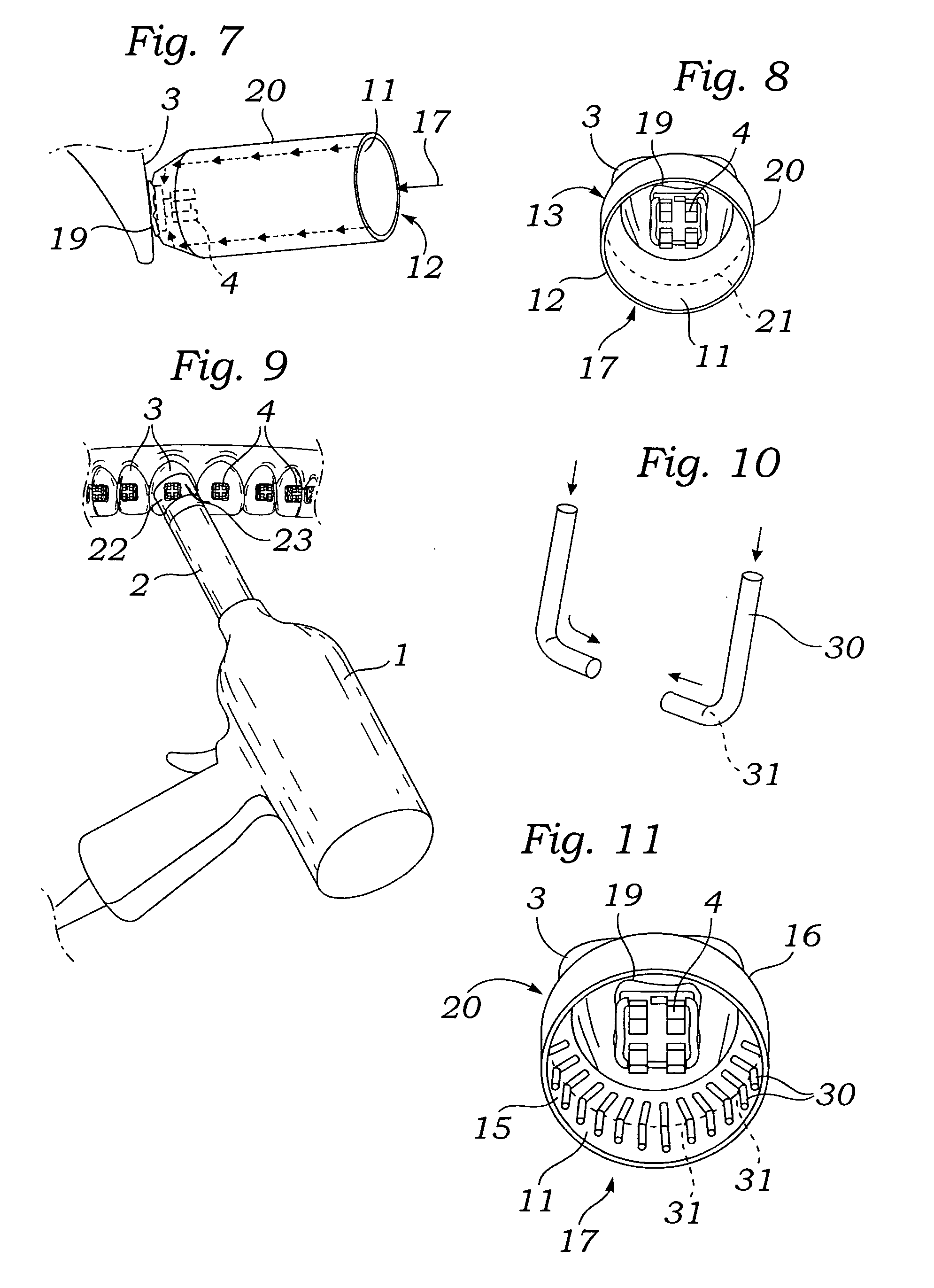
[0006]The light directing and amplifying device is most useful for bonding metal orthodontic brackets to teeth wherein the light cure adhesive is on the tooth side of the orthodontic bracket. The embodiment of the light directing and amplifying device for bonding orthodontic brackets to teeth is comprised of an internally mirrored tubular body with a first end sized to fit the light source and a second end sized to fit over an orthodontic bracket. The second end has an internal curvature, ideally 45 degrees, which directs the light 90 degrees from the light source, directly under the backside of the bracket, thus directly curing the light cure adhesive. The result is the dental curing light need not be directed at the orthodontic bracket from multiple directions, which is time consuming. The light directing and amplifying device provides an amplified light which is directed simultaneously from the buccal and under the bracket base from the occlusal, mesial, gingival and distal directions. The result is a more thorough cure of the orthodontic bracket adhesive in a greatly reduced length of time.
[0007]In one embodiment, the light directing and amplifying device is opaque which shields the patient and operator from any harmful light rays. In another embodiment, the light directing and amplifying device is clear, allowing the operator to see the orthodontic bracket during the curing process. The clear may be amber colored which filters out any harmful light rays. In another embodiment, fiber optic strands are positioned longitudinally on the inner wall of the tubular body and turn inwards 90 degrees at the second end in order to direct the light under the bracket base.

Problems solved by technology

The result is the dental curing light need not be directed at the orthodontic bracket from multiple directions, which is time consuming.

Method used


Image

  • Light directing and amplifying device
  • Light directing and amplifying device
  • Light directing and amplifying device

Examples


Embodiment Construction

[0020]Referring to FIGS. 1, 2, 4 and 9 the light source for curing photosensitive light-cure dental fillings and adhesives is a dental curing device 1. The dental curing device 1 often contains an optic light guide 2 that carries the light to the tooth 3, as shown in FIGS. 2 and 9. Referring to FIG. 2, the light directing and amplifying device 10 is attached to the light emitting end 5 of the optic light guide 2 and the light directing and amplifying device 10 light outlet 18 is held over an orthodontic bracket 4 which has been placed on a tooth 3. The dental curing light 1 is activated until the light cure adhesive 19, as shown in FIG. 6, is hardened. In FIG. 3 an embodiment of the light directing and amplifying device 10 is comprised of a tubular body 16 with a light inlet 17 first end 12, a light outlet 18 second end 13, an exterior 14 and an interior 15 with a mirror coating 11. The mirror coating 11 amplifies the light. The embodiment in FIG. 3 is most useful for accelerating t...


PUM


Abstract

The present invention is directed to a light directing and amplifying device for attachment to a dental curing device used in light cure bonding orthodontic brackets to teeth wherein an internal mirror directs the light 90 degrees from the light source, directly under the back side of the bracket, thus directly curing the light cure adhesive enhancing the cure and rate of cure.

Description

BACKGROUND OF THE INVENTION[0001]Photo curable dental adhesives are frequently used to bond orthodontic brackets to teeth. The dental adhesives are cured by exposure to light from a dental curing device. Dental curing devices are used to create a beam of light of an appropriate wavelength to cause curing of photosensitive materials. Various sources of light have been used within curing lights. The source of light may be a halogen bulb, a Xenon bulb, plasma arc and, more recently, light emitting devices herein referred to as LEDs. Radiant energy is transmitted from the lamp in the lamp assembly through an optic light guide. Optic guides have been necessary on the larger dental curing lights due to the accessibility and size constraints of the mouth. Optic light guides are typically 8-13 mm in diameter, and utilize a round tip at the distal end.[0002]The procedure of bonding metal brackets on teeth has posed a particular problem for the light cure technique. The bracket adhesive is on...

Claims


Application Information

Patent Timeline
Patent Type & Authority Applications(United States)
IPC IPC(8): A61C3/00A61C5/04
CPCA61C5/04A61C19/004A61C7/146A61C5/50
Inventor GRAHAM, NEIL JOHN
Owner GRAHAM NEIL JOHN
Learn More