
Hologram Color Filter, Method for Fabricating the Same, and Color Liquid Crystal Display Comprising It

Inactive Publication Date: 2008-07-10
SUMITOMO ELECTRIC IND LTD
View PDF5 Cites 7 Cited by
  • Summary
  • Abstract
  • Description
  • Claims
  • Application Information

AI Technical Summary

Benefits of technology

[0035]In view of the above-described situation in the prior art, an object of the present invention is to improve the light utilization efficiency and resistance to heat of a hologram color filter having at least one of a light-separating function and a microlens function. Another object of the present invention is to offer a color liquid-crystal-display unit that has high brightness and that is improved in color balance.Means to Solve the Problem
[0050]The present invention uses a DLC film that can create large refractive-index variation and that has excellent resistance to heat to produce a hologram color filter having at least one of a light-separating function and a microlens function. Therefore, the produced hologram color filter can not only increase the utilization efficiency of light but also have significantly improved resistance to heat. The use of the improved hologram color filter enables the offering of a color liquid-crystal-display unit having high brightness and improved color balance.

Problems solved by technology

Such a three-panel-type color liquid crystal projector requires not only three expensive liquid crystal panels but also a large number of optical components to separate a lightwave or combine three lightwaves having different colors.
In other words, the three-panel-type color liquid crystal projector is not only high-cost but also difficult to be miniaturized.
Consequently, the diffraction grating as shown in FIG. 10 must be formed by using the electron-beam drawing, which is unsuitable for the industrial mass production.
For example, as in a photopolymer hologram film, when the refractive-index difference, Δn, is as small as at most 0.04, it is difficult to obtain a hologram film that has a small wavelength dependence of the diffraction efficiency.

Method used


Image

  • Hologram Color Filter, Method for Fabricating the Same, and Color Liquid Crystal Display Comprising It
  • Hologram Color Filter, Method for Fabricating the Same, and Color Liquid Crystal Display Comprising It
  • Hologram Color Filter, Method for Fabricating the Same, and Color Liquid Crystal Display Comprising It

Examples


Embodiment Construction

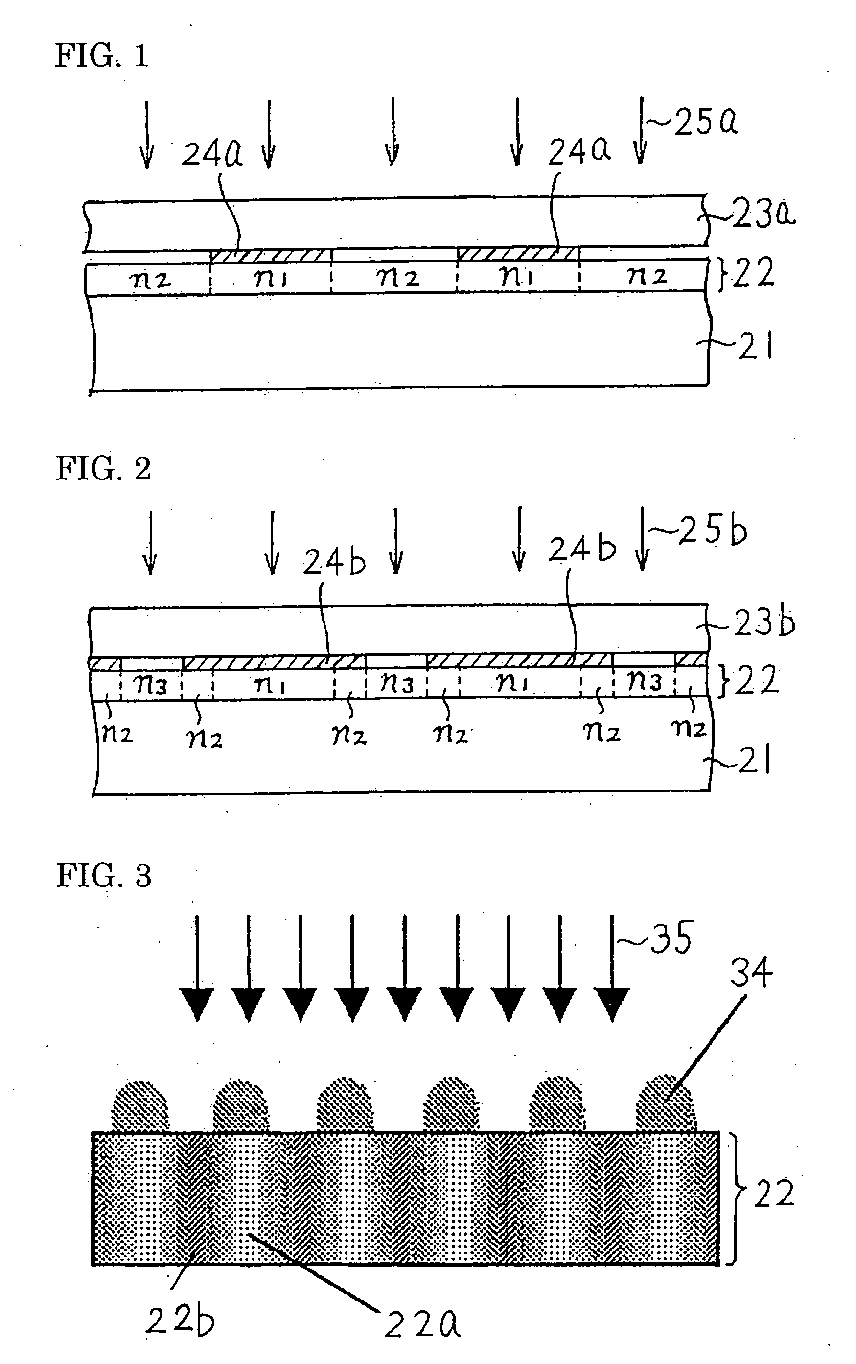
[0066]First of all, in achieving the present invention, the present inventors confirmed that the application of an energy beam onto a light-transmitting DLC film can increase its refractive index. Such a DLC film can be formed on a glass substrate, a polymer substrate, and other various light-transmitting substrates by the plasma chemical vapor deposition (CVD). The light-transmitting DLC film obtained by the plasma CVD usually has a refractive index of about 1.55.

[0067]As the energy beam for increasing the refractive index of the DLC film, an ion beam, a synchrotron radiation (SR) lightwave, an electron beam, and the like can be used. For example, when an He ion is implanted with a dose of 5×1017cm2 at an acceleration voltage of 800 keV, the amount of refractive-index variation, Δn, can be increased to about 0.65. The ion implantation using H, Li, B, C, or the like can also similarly modulate the refractive index. In addition, the application of an SR lightwave having a spectrum of...


PUM


Abstract

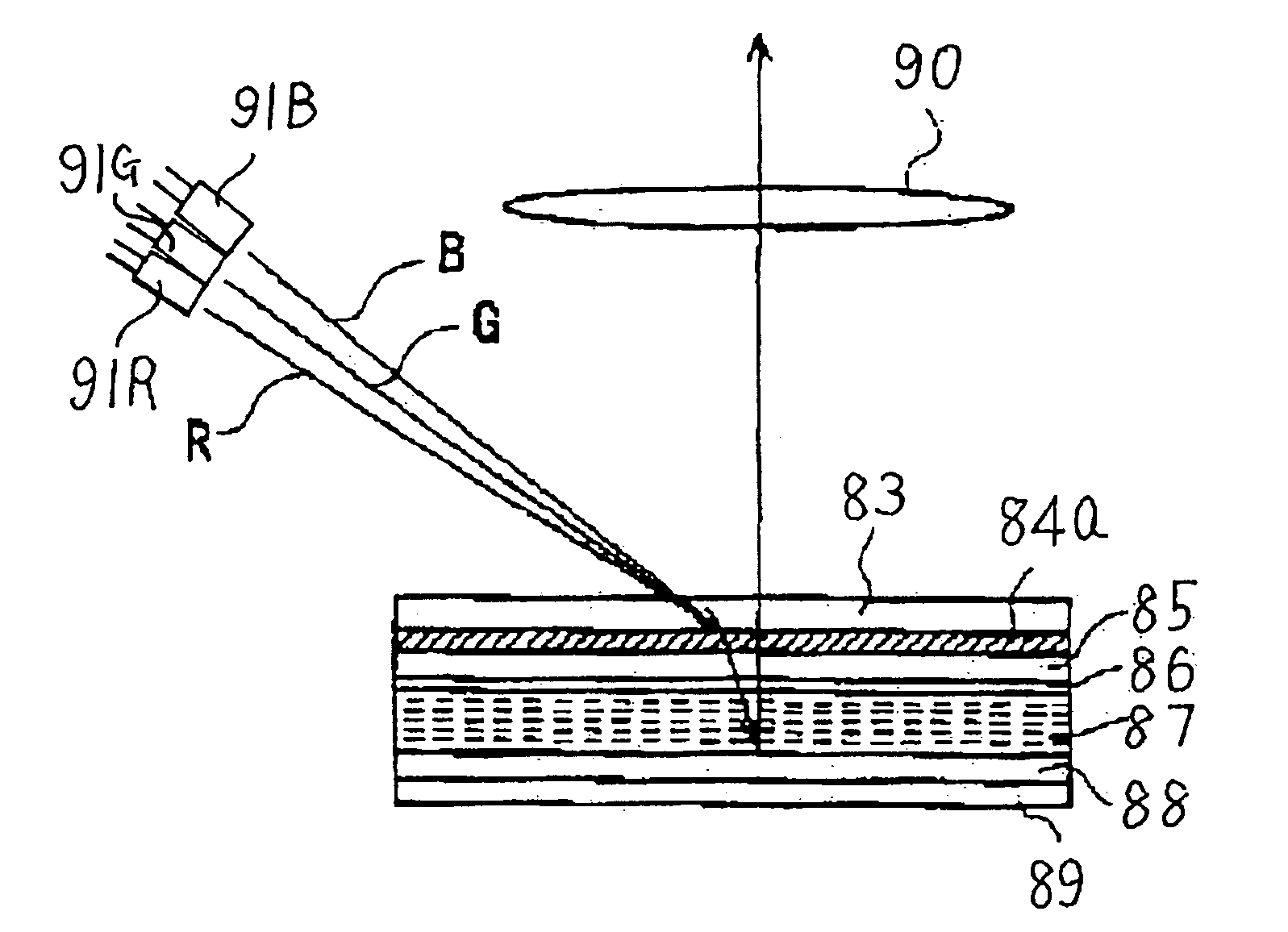
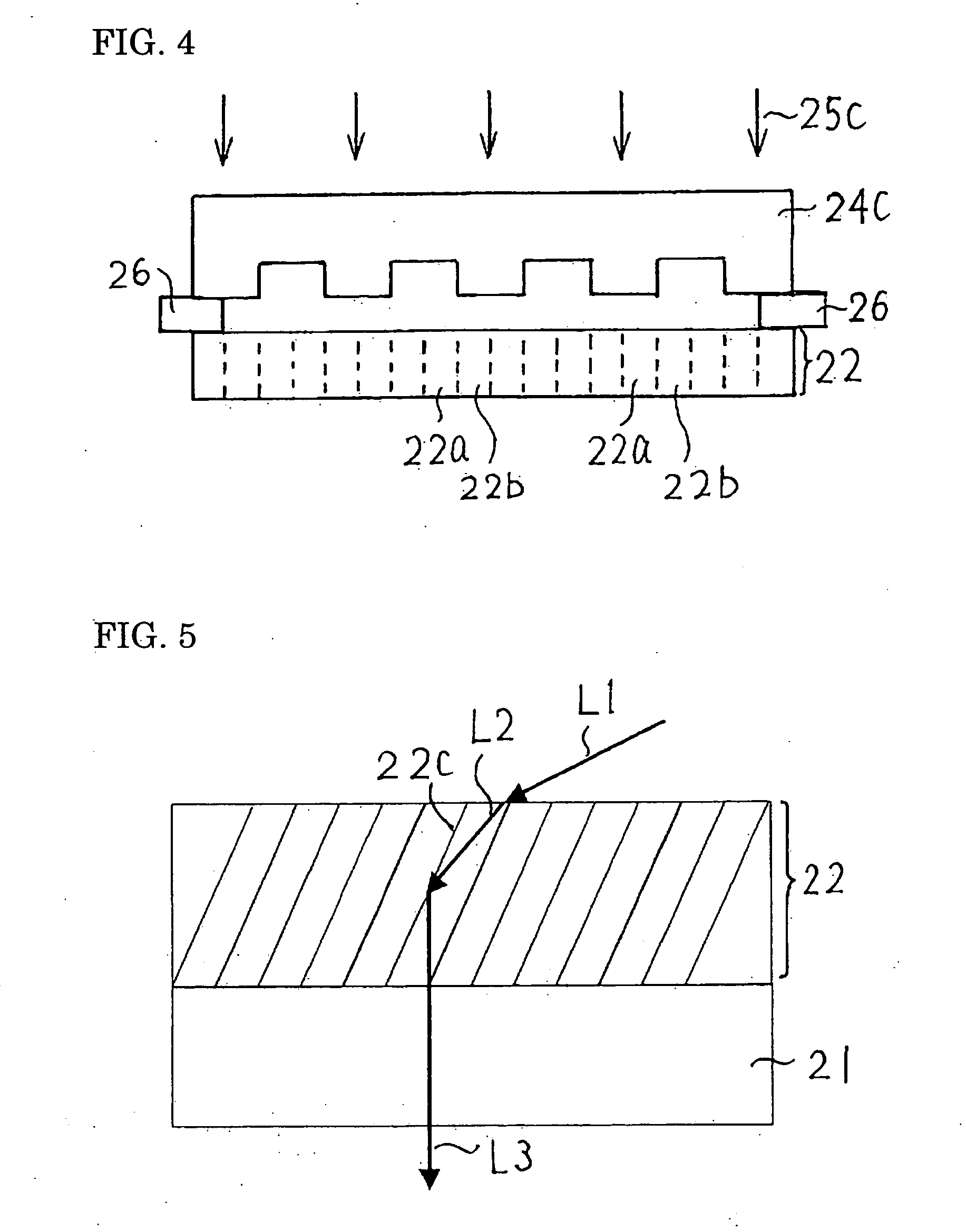
A hologram color filter diffraction-separates an incident lightwave using a hologram to project thus separated lightwaves having different-wavelengths at intended positions with a specified spatial period. The hologram color filter comprises a light-transmitting substrate (21) and a light-transmitting diamond-like-carbon (DLC) film (22) formed on the substrate. In the DLC film, a relatively-low-refractive-index belt-shaped region (n1, 22a) and a relatively-high-refractive-index belt-shaped region (n2, 22b) are placed alternately.

Description

TECHNICAL FIELD[0001]The present invention relates to a hologram color filter and a color liquid-crystal-display unit incorporating the filter, in particular, a hologram color filter having at least one of a light-separating function and a microlens function and an improvement of a color liquid-crystal-display unit incorporating the filter.BACKGROUND ART[0002]In recent years, various types of color liquid-crystal-display units have been put in practical use. As one of these color liquid-crystal-display units, a color liquid crystal projector is used. The color liquid crystal projector has many types, and each of them incorporates three liquid crystal panels. More specifically, a red-color.(R) optical image, a green-color (G) optical blue-color (B) optical image are separately displayed by the three liquid crystal panels. The three optical images having different colors are combined with a optical system to project on a screen as a full-color image.[0003]Such a three-panel-type color...

Claims


Application Information

Patent Timeline
IPC IPC(8): G02B5/32G03H1/04G02B1/02G02B5/18G02B5/20G02F1/1335
CPCG02B1/02G02F1/133516G02B5/203G02B5/20G02F1/1335G03H1/02
Inventor USHIRO, TOSHIHIKOODA, KAZUHIKOOKUBO, SOICHIROMATSUURA, TAKASHI
Owner SUMITOMO ELECTRIC IND LTD
Learn More