
Gravity Gradiometer

a gravity gradiometer and gravity technology, applied in the field of gravity gradiometers, can solve the problem of relatively complicated instruments disclosed in the application of such instruments

Active Publication Date: 2008-07-10
TECHNOLOGICAL RESOURCES
View PDF72 Cites 47 Cited by
  • Summary
  • Abstract
  • Description
  • Claims
  • Application Information

AI Technical Summary

Benefits of technology

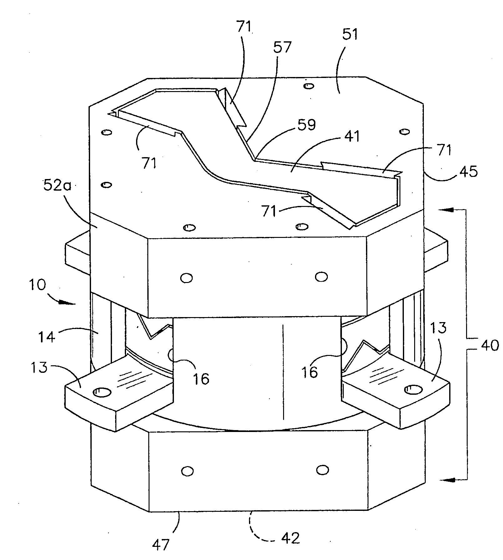
[0019]Preferably the masses are provided in a housing and are connected to the housing by a flexure web, the housing having a peripheral wall, the screw members being located in bores in the masses and the peripheral wall having holes for registering with the bores so that a tool can be passed through the holes into the bores to adjust the position of the screw members in the masses to balance the masses.

Problems solved by technology

The instrument disclosed in that application is relatively complicated in that it includes a large number of parts and is relatively heavy which is a disadvantage particularly in airborne applications.

Method used


Image

  • Gravity Gradiometer
  • Gravity Gradiometer
  • Gravity Gradiometer

Examples


Embodiment Construction

[0055]FIG. 1 is a schematic view of a gravity gradiometer according to the preferred embodiment of the invention.

[0056]The gradiometer shown in FIG. 1 comprises a double walled Dewar 1 which is supported in an external platform 2. The external platform 2 enables adjustment of the Dewar and therefore the contents of the Dewar about three orthogonal axes. The external platform 2 is generally known and its adjustment by suitable motors or the like is also known. Thus, a detailed description will not be provided.

[0057]A vacuum canister 3 is provided in the Dewar and the Dewar is supplied with liquid gas such as liquid helium He so that the gradiometer can operate at cryogenic temperature. The Dewar 1 is closed by an end plate 4 which includes connectors 5a for connecting electrical leads (not shown) to external components (not shown).

[0058]The canister 3 is closed by an end plate 9 which includes connectors 5b for connecting electric leads (not shown) to the connectors 5a. The gradiomet...


PUM


Abstract

A gravity gradiometer is disclosed which has a sensor in the form of bars (41 and 42) which are supported on a mounting (5) which has a first mount section (10) and a second mount section (20). A first flexure web (33) pivotally couples the first and second mount sections about a first axis. The second mount has a first part (25), a second part (26) and a third part (27). The parts (25 and 26) are connected by a second flexure web (37) and the parts (26 and 27) are connected by a third flexure web (35). The bars (41 and 42) are located in housings (45 and 47) and form a monolithic structure with the housings (45 and 47) respectively. The housings (45 and 47) are connected to opposite sides of the second mount section 20. The bars (41 and 42) are connected to their respective housings by flexure webs (59). Transducers (71) are located in proximity to the bars for detecting movement of the bars to in turn enable the gravitational gradient tensor to be measured. A calibration sensor is provided for sensing whether the masses are balanced at room temperature so the balance of the masses can be adjusted by adjustable screws to balance the masses for cryogenic operation of the gradiometer. The calibration sensor comprises a resonant circuit (400, 410) and an oscillator (414). The resonant circuit includes a capacitor (400) which is formed by part of the sensor mass and a space plate (405).

Description

FIELD OF THE INVENTION[0001]This invention relates to a gravity gradiometer, and in particular, but not exclusively, to a gravity gradiometer for airborne use. The invention has particular application for measuring diagonal and off-diagonal components of the gravitational gradient tensor.BACKGROUND OF THE INVENTION[0002]Gravimeters are widely used in geological exploration to measure the first derivatives of the earth's gravitational field. Whilst some advances have been made in developing gravimeters which can measure the first derivatives of the earth's gravitational field because of the difficulty in distinguishing spatial variations of the field from temporal fluctuations of accelerations of a moving vehicle, these measurements can usually be made to sufficient precision for useful exploration only with land-based stationary instruments.[0003]Gravity gradiometers (as distinct from gravimeters) are used to measure the second derivative of the gravitational field and use a sensor ...

Claims


Application Information

Patent Timeline
Patent Type & Authority Applications(United States)
IPC IPC(8): G01V7/00
CPCG01V7/16
Inventor VAN KANN, FRANK JOACHIMWINTERFLOOD, JOHNMANN, ANTHONY GORDON
Owner TECHNOLOGICAL RESOURCES
Learn More