Method and apparatus for forming image

a technology of input apparatus and output control, which is applied in the direction of picture signal generators, solid-state device signal generators, television systems, etc., can solve the problems of reducing the distance between the inter-wires of the ccd line sensor, affecting the output signal, so as to prevent the noise of the drive signal and good image information

Inactive Publication Date: 2008-07-03
KK TOSHIBA +1
View PDF3 Cites 0 Cited by
  • Summary
  • Abstract
  • Description
  • Claims
  • Application Information

AI Technical Summary

Benefits of technology

[0015]The object of the present invention is to provide an image input apparatus and an output control method capable of obtaining good image information by preventing noise of a drive signal from being superimposed on an output signal waveform.

Problems solved by technology

However, the amount of light of a generally used white xenon lamp is limited.
However, owing to the high integration density and small size, the inter-wire distance in the CCD line sensor decreases, and it becomes difficult to keep an area for a guard-ring pattern, etc. for preventing mixing of radiant noise.
Furthermore, since high-speed driving is required, a large current is needed for internal control signals.
Although driving with a large current is required, protection against internal radiant noise is not provided.
Thus, noise is possibly superimposed on internal wiring.
In fact, there is a CCD line sensor wherein induced noise is superimposed on an output signal and an output waveform is disturbed.
On the other hand, it has such a disadvantage that noise of a drive signal tends to be superimposed on an output signal waveform.
If such noise is superimposed, good image information cannot be obtained.

Method used


Image

  • Method and apparatus for forming image
  • Method and apparatus for forming image
  • Method and apparatus for forming image

Examples


Embodiment Construction

[0035]Embodiments of the present invention will now be described with reference to the accompanying drawings.

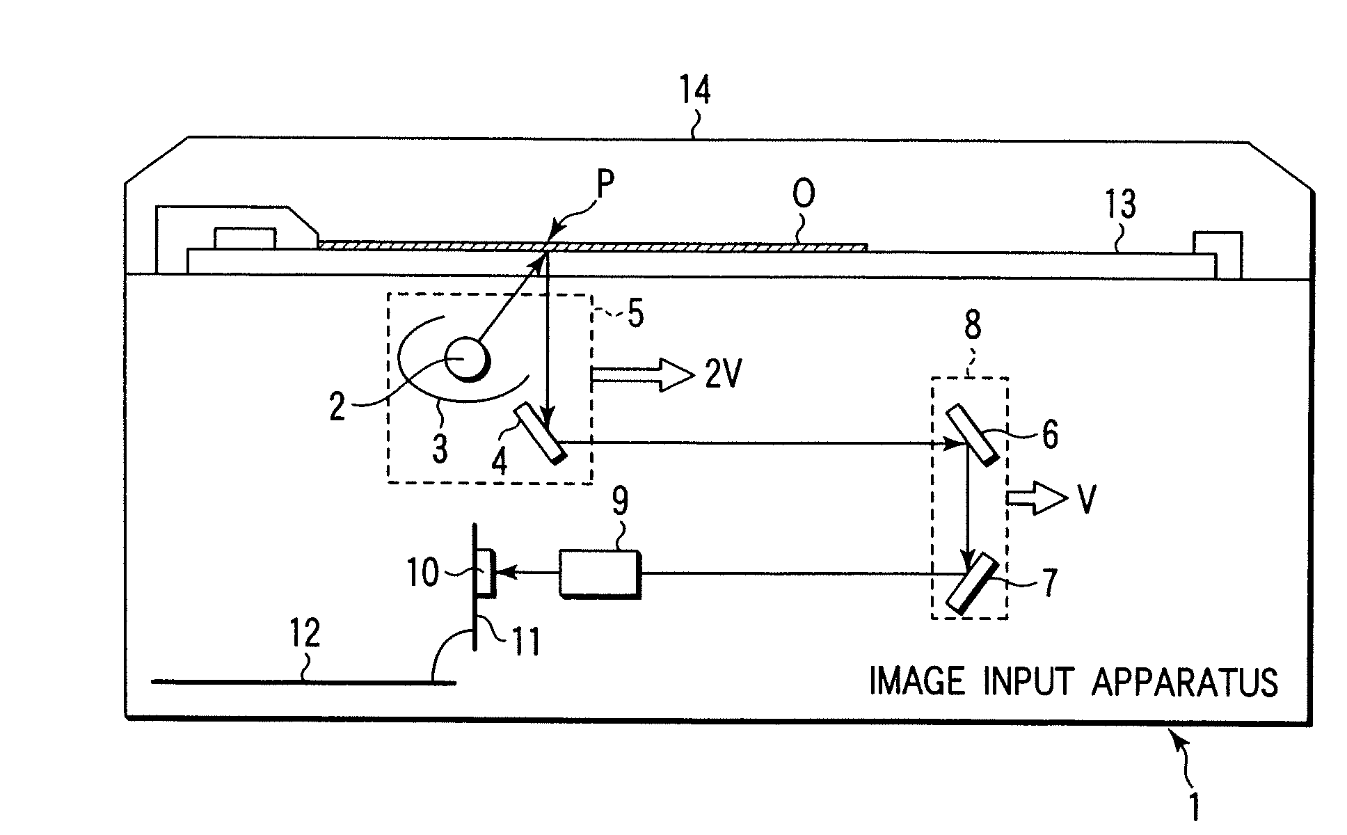
[0036]FIG. 1 shows an image input apparatus 1 using a 4-line CCD sensor according to the present invention. The image input apparatus 1 is an apparatus for reading image information on an original in units of a line corresponding to a resolution.

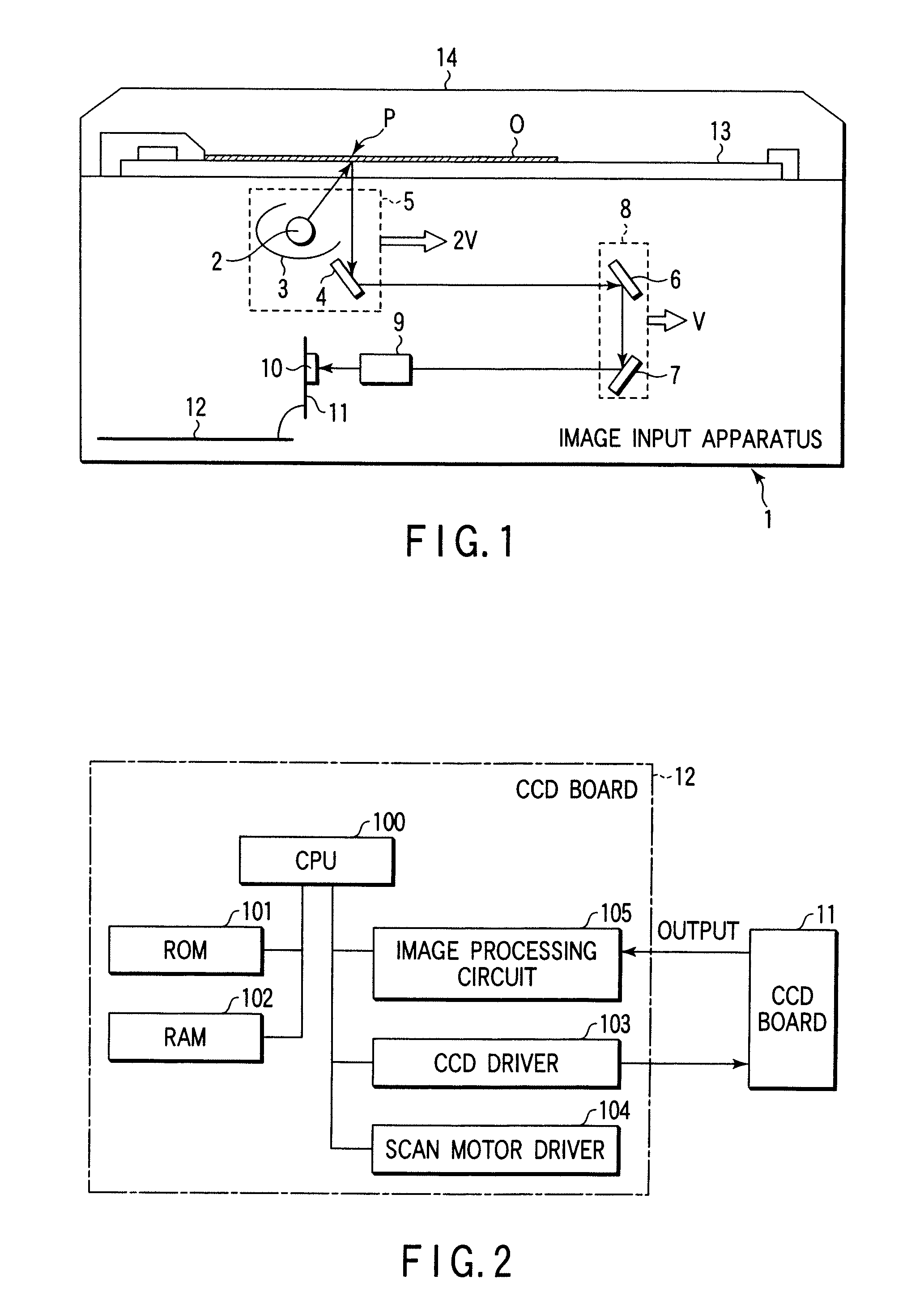
[0037]The image input apparatus 1 comprises a first carriage 5 including a light source 2, a reflector 3 for adjusting a luminous intensity distribution of the light source 2, and a first mirror 4; a second carriage 8 including a second mirror 6 and a third mirror 7; a converging lens 9; a 4-line CCD sensor 10; a CCD board 11 on which the 4-line CCD sensor 10 and sensor drive circuits (not shown) are mounted; and a CCD control board 12 having a control circuit for controlling the 4-line CCD sensor 10 and an image processing circuit for processing output signals from the 4-line CCD sensor 10.

[0038]The operation of the image input appar...


PUM


Abstract

When a monochromatic original is read, a control is effected to transfer a charge accumulated in a monochromatic photodiode array to a rear stage, and not to accumulate charges in respective color photodiode arrays. When a color original is read, a control is effected to transfer charges accumulated in the respective photodiode arrays and not to accumulate a charge in the monochromatic photodiode array.

Description

CROSS-REFERENCE TO RELATED APPLICATIONS[0001]The present application is continuation of U.S. application Ser. No. 10 / 378,066, filed Mar. 4, 2003, the entire contents of which are incorporated herein by reference.BACKGROUND OF THE INVENTION[0002]The present invention relates to an image input apparatus and an output control method, for example, in a color scanner or a color digital copying machine, which reads image information by scanning an original using a color CCD line sensor.[0003]A 4-line CCD sensor has conventionally been marketed as a CCD line sensor used in a reduction optical system. The 4-line CCD sensor includes a sensor section wherein color filters are not arranged on a light-receiving surface of a photodiode array, and a 3-line CCD sensor wherein color filters having characteristics of the optical three primary colors of RED, GREEN and BLUE.[0004]In order to reduce a unit device price of a CCD sensor and to compose an optical system using inexpensive parts, there is a...

Claims


Application Information

Patent Timeline
Patent Type & Authority Applications(United States)
IPC IPC(8): H04N1/04H04N1/19H04N1/028H04N1/191H04N1/48H04N9/04
CPCH04N1/486H04N9/045H04N3/1581H04N25/701H04N25/70
Inventor SAKAKIBARA, JUN
Owner KK TOSHIBA
Why Eureka
Try Eureka