
High efficiency heating resistor comprising an oxide, liquid ejecting head and apparatus using the same

a technology of heating resistor and oxide, which is applied in the direction of ohmic-resistance heating, printing, inking apparatus, etc., can solve the problems of no other materials meeting the above requirements except the conventional materials, and the material can exhibit degradation, so as to improve control the electric resistivity. , the effect of improving the efficiency of heat transfer

Inactive Publication Date: 2008-07-03
KOREA ADVANCED INST OF SCI & TECH
View PDF11 Cites 6 Cited by
  • Summary
  • Abstract
  • Description
  • Claims
  • Application Information

AI Technical Summary

Benefits of technology

[0012]The present invention is directed to new materials for use as a heating resistor. According to the present invention, it is possible to satisfy basic material characteristics as well as easily control the electric resistivity across a wide resistivity range, resulting in the ability to freely design the physical dimensions (i.e., length, width, thickness, etc.) of a heating resistor for use in an ink ejecting device. The materials and heating resistor of the present invention are especially useful for improving the efficiency of heat transfer between a heating resistor and a printing liquid, resulting in higher printing speed and better resolution, as well as a longer device lifetime and more reliable printing head.
[0014]The heating resistor of the present invention has a longer lifetime and is more reliable than conventional heating resistors. Moreover, the heating resistor of the present invention has an electrical resistivity that can be controlled over a broad range, and also has a low temperature coefficient of resistance (TCR) such that a change in device temperature does not appreciably change the electrical resistance of the thermal resistor, enabling printing devices that contain the heating resistors of the present invention to be used repeatedly over an extensive time with no change in device characteristics.
[0016]The present invention is also directed to a high speed / high resolution liquid ejecting system having a strong resistance to the thermal oxidation reaction, an electrical and chemical stability at a high temperature and a good impact-resistance to mechanical impact, such that the heating resistor can be contacted directly a printing liquid without the presence of a protective layer, thereby improving the thermal resistance during heating of the printing liquid.
[0017]The present invention is also directed to a liquid ejecting system having a contact layer between the heating resistor and the electrode, wherein the electric contact resistance between these elements is minimized.

Problems solved by technology

However, these materials can exhibit degradation during thermal cycling.
Moreover, no other materials complying with the above requirements except the conventional materials have been reported.

Method used


Image

  • High efficiency heating resistor comprising an oxide, liquid ejecting head and apparatus using the same
  • High efficiency heating resistor comprising an oxide, liquid ejecting head and apparatus using the same
  • High efficiency heating resistor comprising an oxide, liquid ejecting head and apparatus using the same

Examples


examples

[0070]A plurality of liquid ejecting systems having the structure shown in FIG. 7 (without the structure of the conventional substrate for liquid ejecting head as shown in FIG. 2) were manufactured, and Step Stress Test (SST), Bubble Test (BT) and Printing Durability (PD) were carried out. The heating resistor was formed using a (RuOx)m—(TiOy)n material manufactured in accordance with the present invention, wherein the surface area of the heating resistor available for heating (705) was about 674 μm2 and the resistivity of the (RuOx)m—(TiOy)n material was 108 μΩ·cm.

[0071]FIG. 9 shows the result of an SST test carried out on the liquid ejecting system of the present invention. The SST test was performed as follows: the electrical resistance of the heating resistor was measured continuously while an energy pulse was applied to the heating resistor beginning at a pulse width of 0.5 μsec and increasing in increments of 0.1 μsec up to a pulse width of 4.5 μsec at a frequency of 12 kHz, a...


PUM

PropertyMeasurementUnit
temperature coefficient of resistanceaaaaaaaaaa
resistivityaaaaaaaaaa

Abstract

The present invention is directed to a heating resistor comprising a conducting oxide having an electric conductivity and a nonconducting oxide having insulation or nonconductivity, liquid ejecting heads and apparatus comprising the heating resistors.

Description

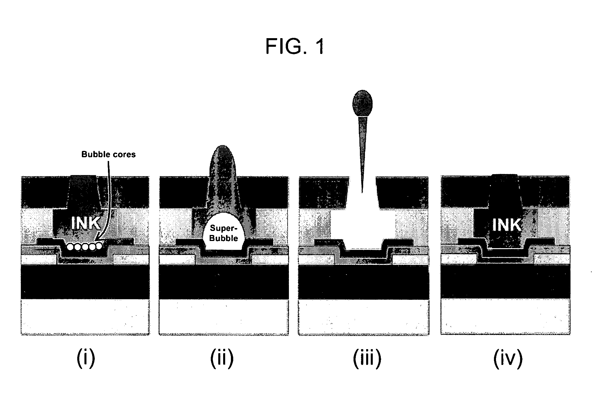
CROSS-REFERENCE TO RELATED APPLICATIONS[0001]This application claims priority to Korean Patent Application No. 10-2007-0000754, filed Jan. 3, 2007, which is incorporated by reference herein in its entirety.BACKGROUND OF THE INVENTION[0002]1. Field of the Invention[0003]The present invention is directed to heating resistors comprising a conducting oxide and a nonconducting oxide and liquid ejecting heads and other devices comprising the heating resistors.[0004]2. Background Art[0005]FIG. 1 provides a schematic representation of the process of liquid ejection from a conventional representative liquid ejecting head. The process of liquid ejecting included the following steps: i) a heating resistor is heated by applying an electric signal to the exterior of the heating resistor, thereby temporarily heating an adjoining printing liquid above a boiling point of the liquid to form bubble cores; ii) the bubble cores grow or coalesce to form a super bubble, and as a result the printing liqui...

Claims


Application Information

Patent Timeline
Patent Type & Authority Applications(United States)
IPC IPC(8): B41J2/05H05B3/10
CPCB41J2/1642B41J2/1643B41J2/1646Y10T29/49083B41J2/14129B41J2/1603B41J2202/03H01C7/00H01C8/00B41J2/01B41J2/05
Inventor KANG, SANG-WONKWON, SE-HUN
Owner KOREA ADVANCED INST OF SCI & TECH
Learn More